A communication time slot arrangement method based on time-triggered bus

A time-triggered, time-slot technology, applied in bus network, data exchange through path configuration, digital transmission system, etc., can solve the problem of time-consuming, labor-intensive, and difficult to communicate time-slot arrangement.

Active Publication Date: 2019-05-17
BEIJING INST OF SPACECRAFT SYST ENG
View PDF5 Cites 0 Cited by
  • Summary
  • Abstract
  • Description
  • Claims
  • Application Information

AI Technical Summary

Problems solved by technology

Not only is it time-consuming and labor-intensive, but also when the system communication requirements change, it is difficult to complete the arrangement of communication time slots in a short time

Method used


Image

  • A communication time slot arrangement method based on time-triggered bus
  • A communication time slot arrangement method based on time-triggered bus
  • A communication time slot arrangement method based on time-triggered bus

Examples


Embodiment 1

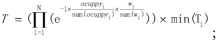
[0024] Embodiment 1, step 1, assuming that the number of nodes in the system is n, wherein for node i, the time length of the communication window occupied by it is ocuppy i , the weight value is w i , the communication period is T i , then the total network communication cycle of the system is:

[0025]

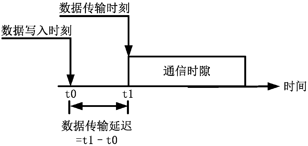
[0026] Step 2. For node i, according to the real-time requirements of its functional communication, set the maximum time delay of node i's transmission time slot as max(delay i ) and the minimum time delay is min(delay i );

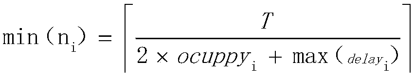
[0027] Then the number of communication slots N of node i i The maximum value of max(N i ) and min(N i )for:

[0028]

[0029]

[0030] Step 3, establish the following equations:

[0031]

[0032] where n i The number of communication slots configured for node i;

[0033] Solve the above equations to obtain the relevant n 1 ~n N Multiple groups of solutions, choose any group to enter step 4;

[0034] Based on the above constrain...

Embodiment 2

[0040] The invention realizes a method for automatically arranging communication time slots based on a time-triggered bus. Take the ARINC659 bus as an example, which is a time-triggered bus. In an integrated electronic system, the processor can operate the peripherals through this bus, and the typical values ​​of various peripheral operations are shown in the following table:

[0041]

[0042]

[0043] According to the above-mentioned input conditions, the calculation process carried out according to the steps of the present invention is as follows:

[0044] (1) Communication frame cycle calculation

[0045] According to the formula shown in step (1), the calculation process of the communication frame period is as follows:

[0046]

[0047] The calculated communication frame period is 24.986ms.

[0048] (2) Calculation of the range of the number of communication windows

[0049] According to the formula shown in step (1), calculate the number of time slots for eac...


PUM


Abstract

The invention discloses a communication time slot arrangement method based on a time trigger bus. The method specifically comprises the following steps of setting the number of nodes in a system as n, wherein a time duration of a communication time slot occupied by a node i is ocuppyi, a weight value is wi and a communication period is Ti for the node I, and computing a total communication period T of a network of the system; establishing a constraint condition equation set for the node i according to the real-time requirements for functional communication of the node i, solving multiple groups of solutions related to n1-nN, selecting any group as a distribution scheme of the number of communication time slots of each node, and arranging the nodes to a queue A from big to small or from small to big according to the distributed number of the communication time slots; selecting the nodes from the queue A in sequence and uniformly arranging the communication time slots corresponding to the selected nodes on a time shaft according to the distributed number of the communication time slots; and if the time arranged by the communication time slot corresponding to the node is occupied, arranging the communication time slot after the occupied time. According to the method, the communication frame period can be periodically and adaptively adjusted according to the functions of each node of the time trigger bus.

Description

technical field [0001] The invention belongs to the technical field of spacecraft integrated electronics, and in particular relates to a method for arranging communication time slots based on a time-triggered bus. Background technique [0002] With the deepening of time-triggered bus in the application of integrated electronic systems, in this application mode, devices or modules usually communicate according to pre-planned time slots, and there is no possibility of conflicts or accidents. However, compared with the previous application methods, it is necessary to complete the pre-arrangement of communication time slots in the system design stage according to the communication requirements of each device or module. Most of the traditional layout methods are done manually by designers. Not only is it time-consuming and labor-intensive, but also when the system communication requirements change, it is difficult to complete the arrangement of communication time slots in a shor...

Claims


Application Information

Patent Timeline
Patent Type & Authority Patents(China)
IPC IPC(8): H04L12/40H04L12/911
CPCH04L12/40H04L47/70
Inventor 程博文刘伟伟于敏芳
Owner BEIJING INST OF SPACECRAFT SYST ENG
Why Eureka
Try Eureka