
A light-transmitting concrete preparation device and preparation method

A light-transmitting concrete and preparation device technology, applied in the direction of supply devices, manufacturing tools, ceramic molding machines, etc., can solve the waste of manpower and time for optical fiber arrangement and fixing, affect the appearance and durability of concrete, and produce low efficiency, etc. problems, to achieve the effect of shortening the construction period, reducing manpower costs, and high accuracy of layout

Active Publication Date: 2019-01-04
中建西部建设西南有限公司 +1
View PDF8 Cites 0 Cited by
  • Summary
  • Abstract
  • Description
  • Claims
  • Application Information

AI Technical Summary

Problems solved by technology

[0003] The preparation methods of light-transmitting concrete mainly include post-positioning method and pre-positioning method. The post-positioning method is to punch holes in semi-rigid concrete and pour transparent resin materials. After the concrete and resin harden, light-transmitting concrete can be obtained, but This preparation method has strict requirements on the quality of the concrete, the size and depth of the perforated holes, the preparation cost is high, and improper operation will affect the appearance and durability of the concrete; , although the problems of the post-positioning method are solved, the arrangement and fixing of the optical fibers waste a lot of manpower and time, the preparation efficiency is low, and the production cost is high

Method used


Image

  • A light-transmitting concrete preparation device and preparation method
  • A light-transmitting concrete preparation device and preparation method
  • A light-transmitting concrete preparation device and preparation method

Examples


Embodiment Construction

[0035] In order to better understand the present invention, the present invention will be further described below in conjunction with the accompanying drawings and specific embodiments.

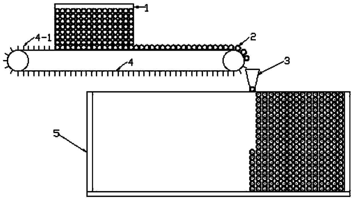
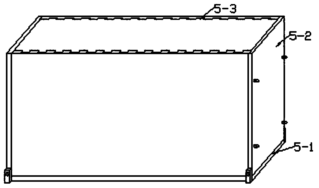
[0036] Such as figure 1 A light-transmitting concrete preparation device shown includes a light-transmitting medium storage bin 1, a forming mold 5 and a conveying device for transporting the light-transmitting medium 2. The bottom of the light-transmitting medium storage bin 1 has an outlet, and the light-transmitting medium The outlet of the medium storage bin 1 is located directly above the input end of the transmission device; the forming mold 5 is provided with an installation groove, which is compatible with the light-transmitting medium 2; the output end of the transmission device is located directly above the installation groove; The axis of the transparent medium 2 is always perpendicular to the conveying direction of the conveying device.

[0037] The transmission device includes a...


PUM

PropertyMeasurementUnit
lengthaaaaaaaaaa
particle sizeaaaaaaaaaa

Abstract

The invention provides a light-transmitting concrete preparation device which comprises a light-transmitting medium storage bin, a forming mold and a conveying device for conveying a light-transmitting medium. The bottom of the light-transmitting medium storage bin is provided with an opening, and the opening of the light-transmitting medium storage bin is located over the input end of the conveying device. An installation groove is formed in the forming mold and matched with the light-transmitting medium. The output end of the conveying device is located over the installation groove. The length direction of the light-transmitting medium is always perpendicular to the conveying direction of the conveying device. The invention further provides a light-transmitting concrete preparation method. The light-transmitting concrete preparation device and method have the beneficial effects that automatic distribution of the light-transmitting medium can be achieved according to the area of a light-transmitting concrete wall and the requirements of the wall for the thickness, the light-transmitting concrete wall meeting requirements is manufactured at a time, the problem that the quality and aesthetics of the wall are affected by splicing of small light-transmitting concrete blocks is avoided, the distribution efficiency is high, production efficiency is improved, and the construction period is shortened.

Description

technical field [0001] The invention relates to a preparation process of light-transmitting concrete, in particular to a preparation device and a preparation method of light-transmitting concrete. Background technique [0002] The traditional concrete structure is single, and the application of architectural decorative concrete breaks the impression and application range of this traditional material. In 2001, Hungarian architect AronLosonczj invented light-transmitting concrete, which made people’s eyes shine. AronLosonczj embedded thousands of light-transmitting optical fibers in the concrete, which made the originally dark concrete have a good decorative effect. For this reason, the world Researchers from various countries have set off a climax in the study of light-transmitting concrete, and have proposed more and more convenient methods for the preparation of light-transmitting concrete. [0003] The preparation methods of light-transmitting concrete mainly include the ...

Claims


Application Information

Patent Timeline
Patent Type & Authority Patents(China)
IPC IPC(8): B28B23/00B28B13/02
CPCB28B13/02B28B23/0037
Inventor 温超凯高育欣陈景徐国栋卢佳林兰聪
Owner 中建西部建设西南有限公司
Learn More