Eureka AIR delivers breakthrough ideas for toughest innovation challenges, trusted by R&D personnel around the world.

Drum winding device

A technology of winding device and drum, which is applied in the direction of transportation and packaging, drill pipes, drill pipes, etc., can solve the problems of adjusting the height of carbon fiber rods, no automatic carbon fiber rod arrangement device, and carbon fiber rods are not neat.

Active Publication Date: 2019-02-15
BC P INC CHINA NAT PETROLEUM CORP +3
View PDF4 Cites 0 Cited by
  • Summary
  • Abstract
  • Description
  • Claims
  • Application Information

AI Technical Summary

Problems solved by technology

[0002] With the continuous emergence of high water-cut oil wells, deep wells, ultra-deep wells, and corrosive oil wells in the development process of major oil fields, the types of development are becoming more and more complex, and the demand and application of carbon fiber rod pumping equipment are becoming more and more extensive, which is in the ascendant. However, there is no carbon fiber rod winding equipment that can be well matched with it, and there is an urgent need to develop a carbon fiber rod winding device dedicated to oil fields
[0003] The existing winding equipment has the following problems: 1. The wound carbon fiber rods are not neat and easy to damage the carbon fiber rods; 2. There is no automatic rod arrangement device for the carbon fiber rods; 3. The height of the carbon fiber rods cannot be adjusted according to the actual working conditions, so that the carbon fiber rods The rod bears more force and is more likely to damage the rod, which reduces the service life of the carbon fiber rod

Method used


Image

  • Drum winding device
  • Drum winding device
  • Drum winding device

Examples


Embodiment Construction

[0042] The above and other technical features and advantages of the present invention will be clearly and completely described below with reference to the accompanying drawings. Obviously, the described embodiments are only some embodiments of the present invention, but not all embodiments.

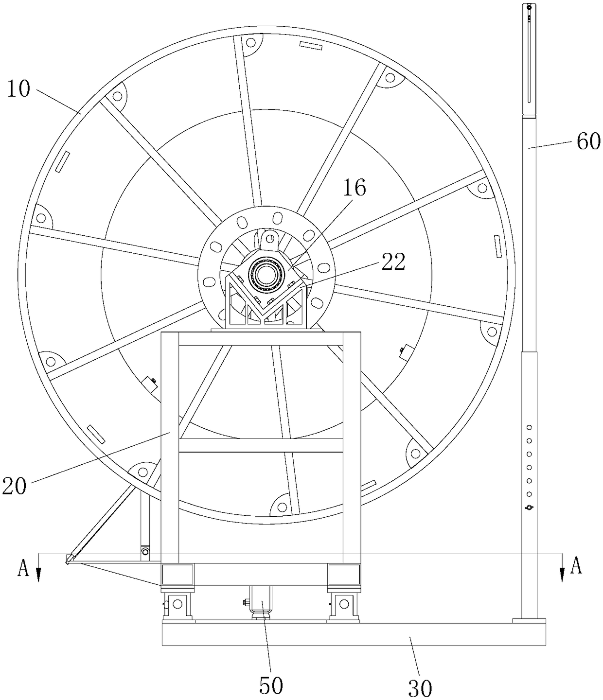
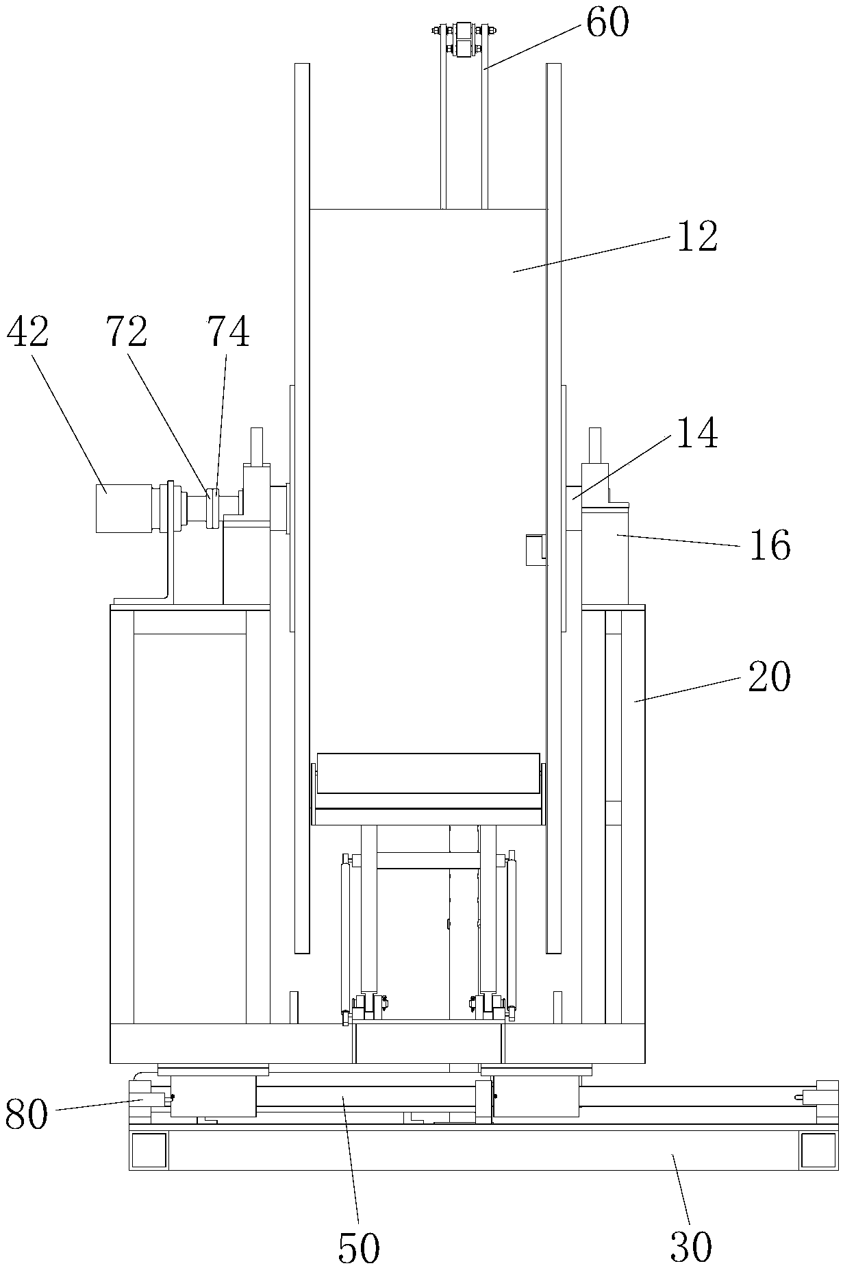
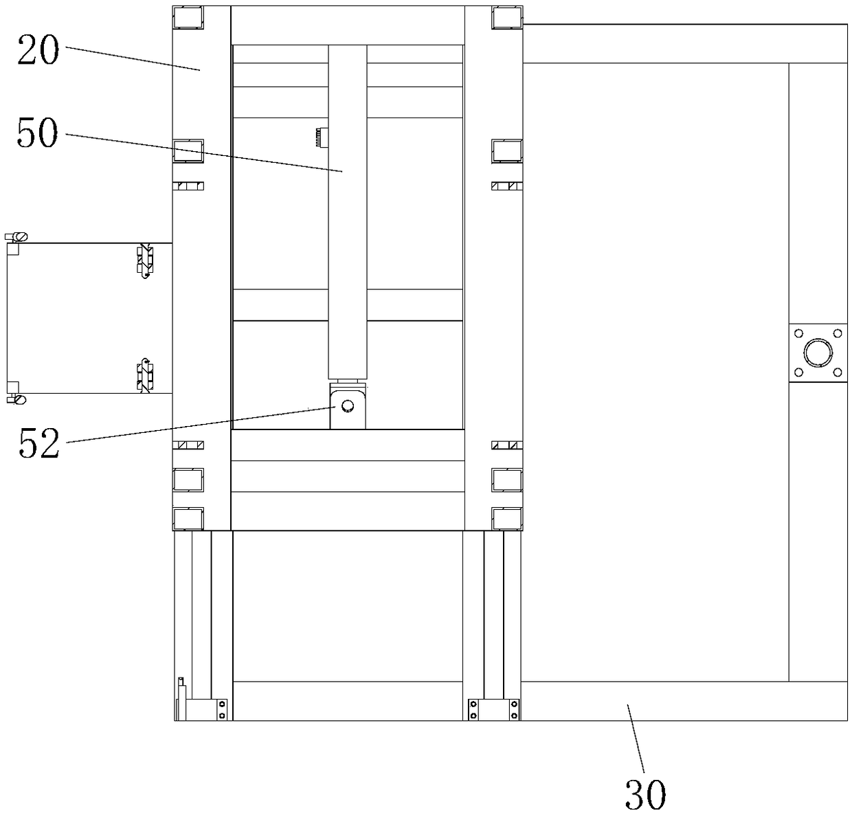
[0043] see figure 1 and figure 2 As shown, the present invention provides a drum winding device, which includes a drum body assembly 10, a drum support base 20, a base 30, a motor 42 with an output shaft, and an electric cylinder 50 with a push rod. The drum body assembly 10 includes a vertical drum 12 and a drum shaft 14. The drum shaft 14 runs through the drum 12 along the center of the drum 12; It can be placed on the base 30 so as to be slidable in the horizontal direction. The output shaft of the motor 42 is connected to the drum shaft 14 and drives the drum shaft 14 to rotate. see image 3 As shown, the electric cylinder 50 is horizontally arranged on the base 30, the telescopi...


PUM


Abstract

The invention provides a drum winding device comprising a base, a drum body assembly, a drum supporting base, a motor with an output shaft, and an electric cylinder with a push rod; the drum body assembly comprises a drum vertically arranged, and a drum shaft penetrating through the drum along the center of the drum; the drum supporting base is arranged on the base slidably in the horizontal direction; both ends of the drum shaft are rotatably connected to the drum supporting base respectively; the output shaft is connected to the drum shaft, and used to drive the drum shaft to rotate; the electric cylinder is arranged on the base horizontally, and the extension direction of the push rod is in parallel with the drum shaft; the extension end of the push rod is connected to the drum supporting base, and used to drive the drum supporting base to slide horizontally in the extension direction of the push rod on the base. In the invention, automatic rod arrangement can be achieved, and carbon fiber rods can be arranged on the drum uniformly in order.

Description

technical field [0001] The invention relates to the technical field of carbon fiber continuous sucker rods, in particular to a device with rollers for winding carbon fiber continuous sucker rods. Background technique [0002] With the continuous emergence of high water-cut oil wells, deep wells, ultra-deep wells and corrosive oil wells in the development process of major oil fields, the types of development are becoming more and more complex, and the demand and application of carbon fiber rod pumping equipment are becoming more and more extensive, which is in the ascendant. However, there is no carbon fiber rod winding equipment that can be well matched with it, and it is urgent to develop a carbon fiber rod winding device dedicated to oil fields. [0003] The existing winding equipment has the following problems: 1. The wound carbon fiber rod is not neat, which is easy to damage the carbon fiber rod; 2. There is no automatic rod arrangement for the carbon fiber rod; 3. The ...

Claims


Application Information

Patent Timeline
Patent Type & Authority Patents(China)
IPC IPC(8): B65H54/02E21B19/22
CPCB65H54/02E21B19/22
Inventor 郝军刘寿军杨高马青杨志敏宋治国吴大飞
Owner BC P INC CHINA NAT PETROLEUM CORP
Why Eureka
Eureka Blog
Learn More