Supercharge Your Innovation With Domain-Expert AI Agents!

Linear led drive thyristor dimming discharge current control circuit

A technology of LED drive and discharge current, which is applied in the field of linear LED drive thyristor dimming discharge current control circuit, can solve the problems of overall efficiency loss and circuit complexity, and achieve improved efficiency, high system reliability, and reduced chips Effect of pin count

Active Publication Date: 2018-12-14
CRM ICBG (WUXI) CO LTD
View PDF7 Cites 0 Cited by
  • Summary
  • Abstract
  • Description
  • Claims
  • Application Information

AI Technical Summary

Problems solved by technology

[0006] In view of the above-mentioned shortcomings of the prior art, the object of the present invention is to provide a linear LED driving thyristor dimming and discharging current control circuit, which is used to solve the problem of linear LED driving thyristor dimming and discharging in the prior art. The circuit of the current control circuit is complicated, and the overall efficiency loss is relatively large.

Method used


Image

  • Linear led drive thyristor dimming discharge current control circuit
  • Linear led drive thyristor dimming discharge current control circuit
  • Linear led drive thyristor dimming discharge current control circuit

Examples


Embodiment Construction

[0078] Embodiments of the present invention are described below through specific examples, and those skilled in the art can easily understand other advantages and effects of the present invention from the content disclosed in this specification. The present invention can also be implemented or applied through other different specific embodiments, and various modifications or changes can be made to the details in this specification based on different viewpoints and applications without departing from the spirit of the present invention.

[0079] see Figure 3 to Figure 5 . It should be noted that the diagrams provided in this embodiment are only schematically illustrating the basic idea of ​​the present invention, and only the components related to the present invention are shown in the diagrams rather than the number, shape and shape of the components in actual implementation. Dimensional drawing, the type, quantity and proportion of each component can be changed arbitrarily ...


PUM


Abstract

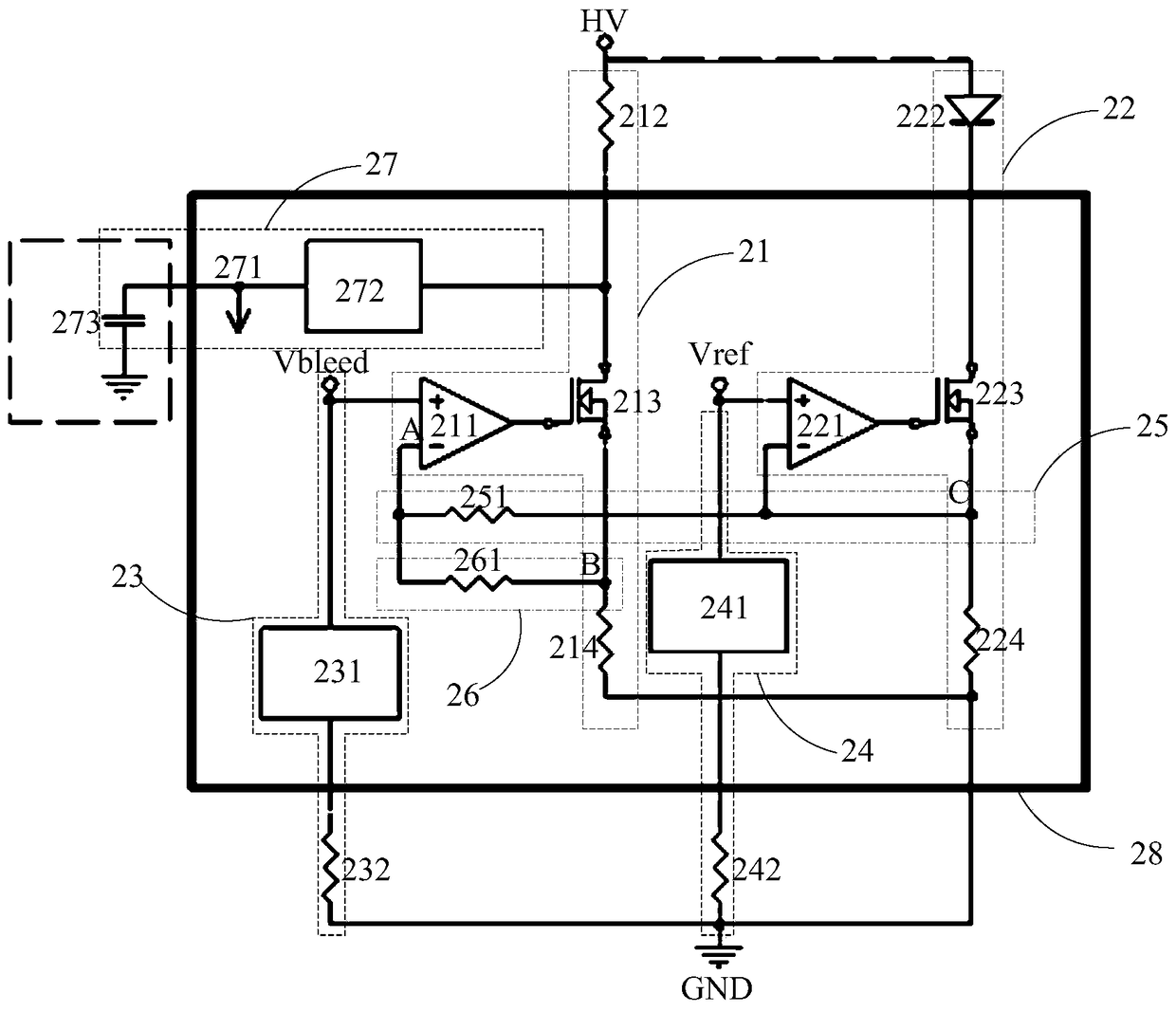
The present invention provides a silicon controlled rectifier dimming leakage current control circuit through linear LED driving. The circuit comprises a voltage output module, a leakage circuit, a LED driving circuit, a first reference voltage module, a second reference voltage module, a first feedback circuit and a second feedback circuit. The current control detection function inherent in the circuit is employed to realize the Bleed detection control function with no need for extra addition of an input current detection resister and detection of the input voltage and the phase angle; the peripheral circuit is simple, and the system reliability is high; the Bleed current can be controlled, the system efficiency loss of the system because the Bleed current cannot be controlled is reduced, and the input current cannot have the uncontrollable peak jumping caused by the switching of the Bleed circuit so as to reduce the interference of the system to the surrounding; the setting of the Bleed current can obtain high precision; and moreover, a Bleed port is employed to supply power for the interior of the chip so as to reduce the number of the chip pins and extend the application range of the chip.

Description

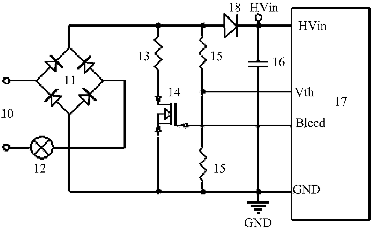
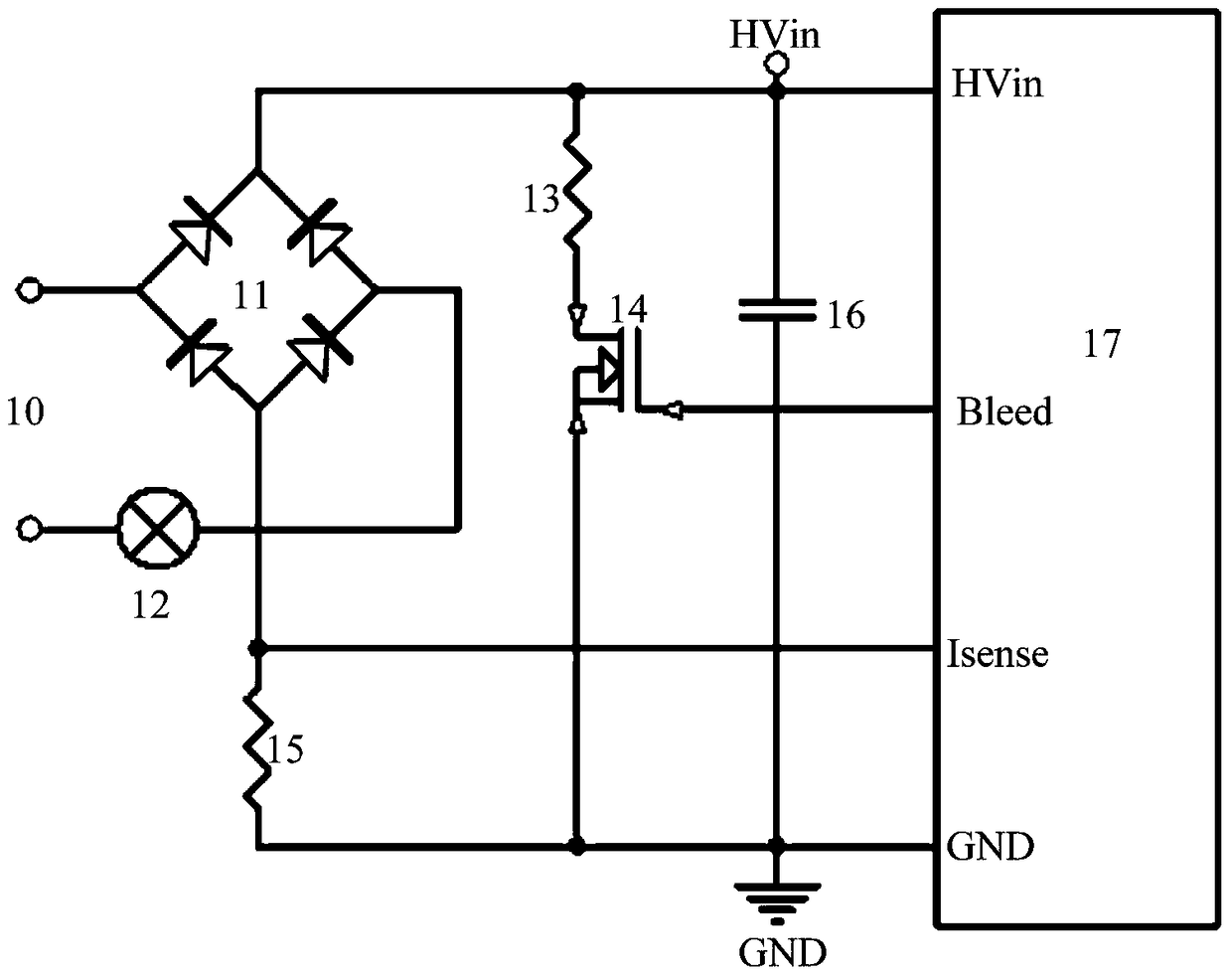
technical field [0001] The invention belongs to the field of LED driving, in particular to a linear LED driving thyristor dimming and discharging current control circuit. Background technique [0002] In the SCR dimming LED drive application, the SCR conduction has a maintenance current requirement. Once the input current is less than the maintenance current, the SCR will be turned off and then restarted, which will cause the LED to flicker. Therefore, it is generally required Add a bleed (Bleed) circuit to meet the maintenance current requirements of the thyristor, so that the thyristor is always turned on within the working range, and avoid the flickering of the LED. [0003] The main problem of thyristor dimming is the detection and control of bleed current. The existing bleed current detection methods include detection of input voltage or phase angle, and detection of input current. [0004] Circuits that detect input voltage or phase angle such as figure 1 As shown, t...

Claims


Application Information

Patent Timeline
Patent Type & Authority Patents(China)
IPC IPC(8): H05B37/02
Inventor 刘军吴泉清王兆坤尤勇李国成罗丙寅胡津华王雷一许林海任会远王玲祝超王玉洁
Owner CRM ICBG (WUXI) CO LTD
Features
  • R&D
  • Intellectual Property
  • Life Sciences
  • Materials
  • Tech Scout
  • Unparalleled Data Quality
  • Higher Quality Content
  • 60% Fewer Hallucinations
Learn More