Heat radiation device and heat radiation assembly

A technology of heat dissipation device and heat dissipation part, which is applied in the direction of heat transfer modification, electrical components, heat exchange equipment, etc. It can solve the problems of low heat dissipation efficiency and increase of the overall weight of electronic devices, and achieve the effect of fast heat dissipation and light weight

Inactive Publication Date: 2017-01-04
HONG FU JIN PRECISION IND WUHAN CO LTD +1
View PDF2 Cites 4 Cited by
  • Summary
  • Abstract
  • Description
  • Claims
  • Application Information

AI Technical Summary

Problems solved by technology

Therefore, the heat dissipation efficiency of the end of the heat sink close to the air inlet is low, and this part of the

Method used


Image

  • Heat radiation device and heat radiation assembly
  • Heat radiation device and heat radiation assembly
  • Heat radiation device and heat radiation assembly

Examples


Embodiment Construction

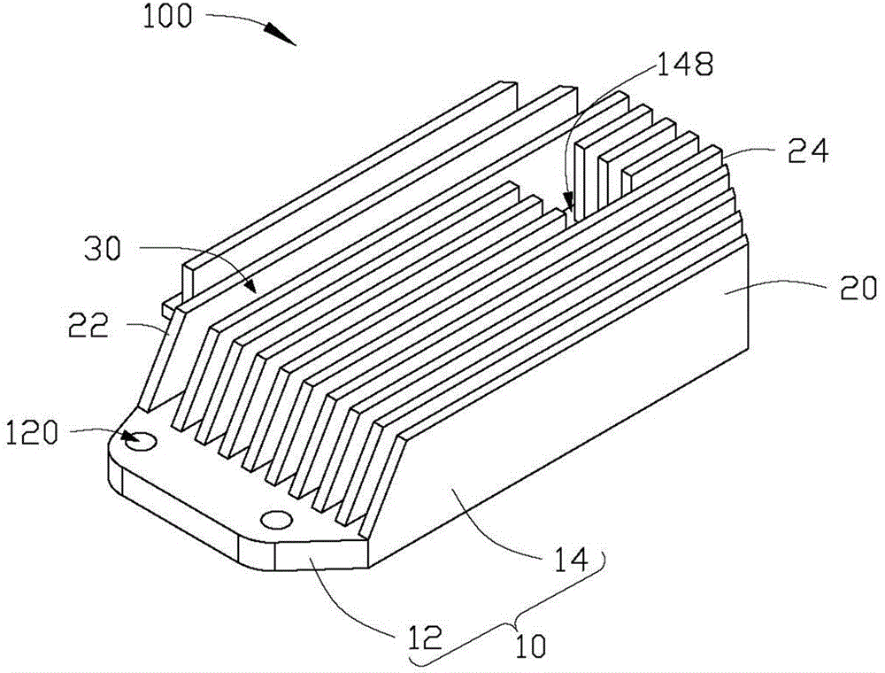
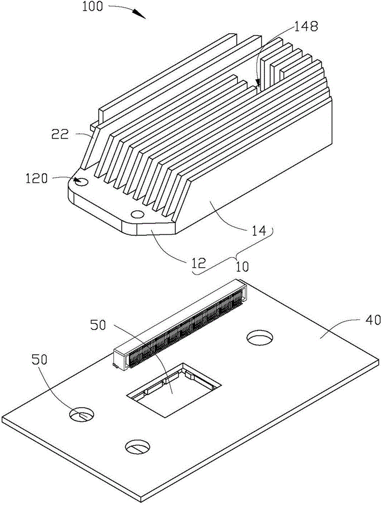
[0023] see Figure 1 to Figure 2 , in a preferred embodiment of the present invention, a heat sink 100 is used to dissipate heat for an electronic device 200, the heat sink 100 includes a plate body 10 and a plurality of fins 20, the plurality of fins 20 from the The board body 10 extends out.

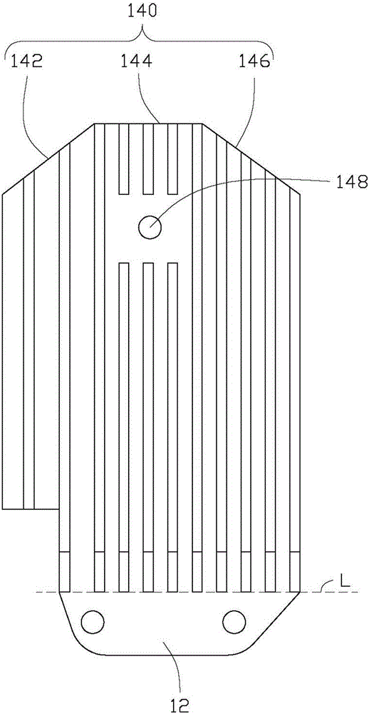
[0024] The board body 10 includes a fixing portion 12 and a heat dissipation portion 14 connected to the fixing portion 12 , and the fixing portion 12 extends from the heat dissipation portion 14 . In one embodiment, the fixing portion 12 is substantially in the shape of an isosceles trapezoid, and is located on the same plane as the heat dissipation portion 14 . The fixing portion 12 defines two fixing holes 120 . The heat dissipation portion 14 defines a locking hole 148 . The heat dissipation portion 14 includes a side portion 140 , the side portion 140 is located at an end of the heat dissipation portion 14 away from the fixing portion 12 , and includes a first side 142 , a seco...


PUM


Abstract

The invention discloses a heat radiation device. The heat radiation device comprises a plate body and a plurality of fins extended out from the plate body. The plate body comprises a fixing part disposed on one side of an air inlet and a heat radiation part connected with the fixing part. The heat radiation part comprises a lateral part, which comprises at least two connected lateral sides. Every fin comprises an inclined surface and a lateral surface opposite to the inclined surface, and the inclined surfaces of the plurality of fins are arranged on a straight line parallel to the plate body, and the lateral surfaces of the plurality of fins are correspondingly aligned with the side edges of the lateral sides of the at least two lateral sides. The invention also relates to a heat radiation assembly.

Description

technical field [0001] The invention relates to a heat dissipation device and a heat dissipation assembly. Background technique [0002] Electronic devices generate heat during operation. If the heat cannot be dissipated in time, the electronic devices will fail to work or shorten their service life due to overheating. The internal temperature of the projector is higher than that of ordinary electronic devices due to the heat generated by the bulb during operation. Generally, a heat sink and a fan are used inside the projector to dissipate heat. However, the existing heat sink structure usually has a plurality of heat dissipation fins evenly distributed on a plate body, but the temperature of the end of the heat sink near the air inlet is much lower than the temperature of the end far away from the air inlet. Therefore, the heat dissipation efficiency of the end of the heat sink near the air inlet is low, and this part of the heat sink has a certain weight and occupies spa...

Claims


Application Information

Patent Timeline
IPC IPC(8): H05K7/20
CPCG06F1/20H01L23/367H01L23/4006F28F13/00H01L23/34
Inventor 叶锦文彭志坚
Owner HONG FU JIN PRECISION IND WUHAN CO LTD
Why Eureka
Try Eureka