Center shaft for disc filter

A technology of disc filter and central shaft, which is applied in the direction of filtration separation, mobile filter element filter, separation method, etc., can solve the problems of poor strength and rigidity of the central shaft, occupy a large space, reduce energy consumption, etc., and achieve strength and rigidity Improvement, beautiful appearance, and the effect of reducing energy consumption

Active Publication Date: 2017-01-11
LUOYANG MINING MACHINERY ENG DESIGN & RES INST
View PDF5 Cites 0 Cited by
  • Summary
  • Abstract
  • Description
  • Claims
  • Application Information

AI Technical Summary

Problems solved by technology

[0005] The purpose of the present invention is to overcome the deficiencies in the prior art and provide a central shaft for disc filters, which solves the problems of poor strength and rigidity of the central shaft, excessive diameter, large space occupation and energy consumption, and can effectively Fix the fan plate, and at the same time, it is easier to design a flow channel that matches the material, thereby reducing energy consumption

Method used


Image

  • Center shaft for disc filter
  • Center shaft for disc filter
  • Center shaft for disc filter

Examples


Embodiment 1

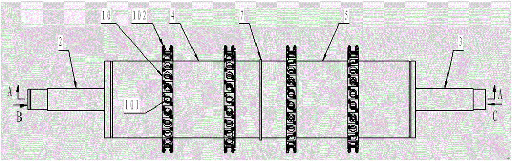
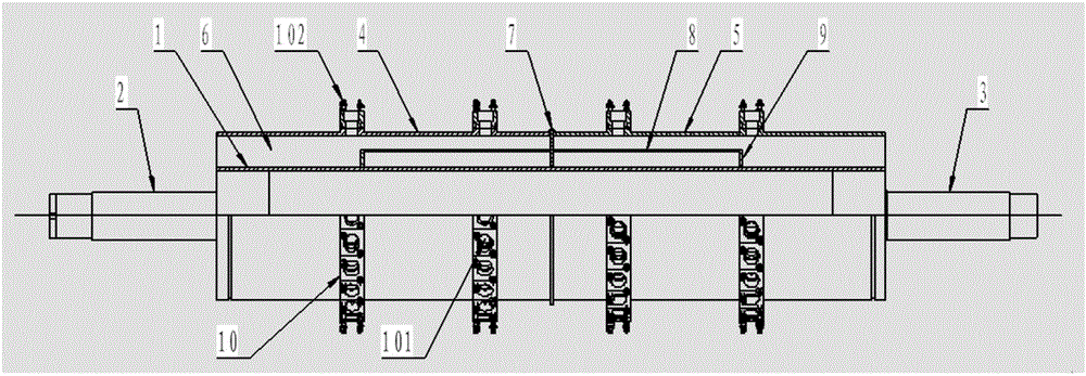
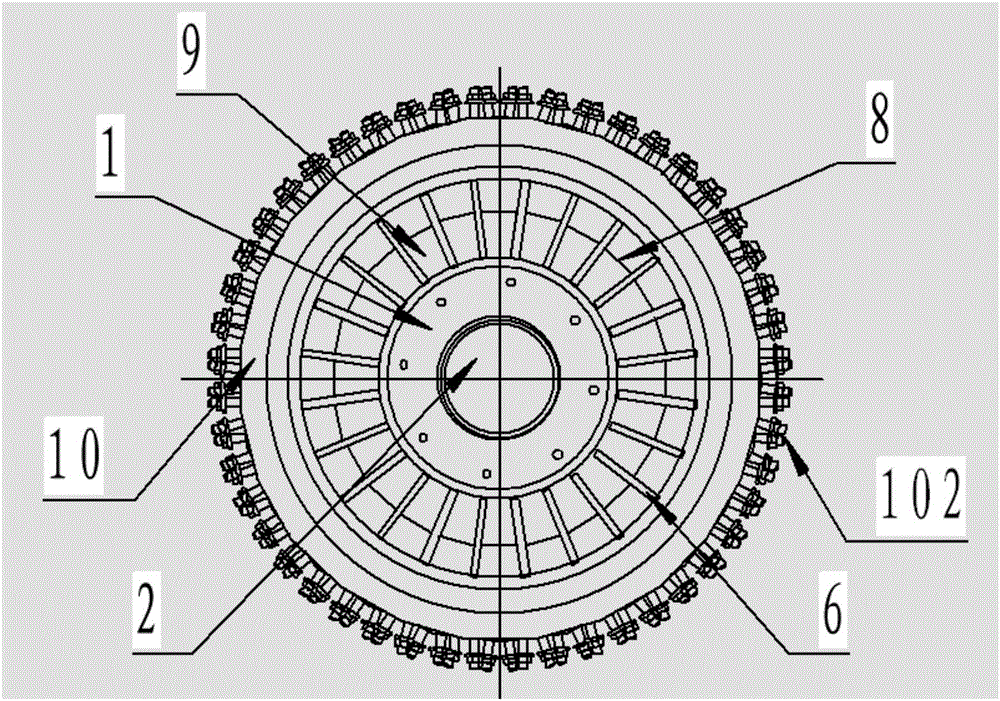
[0025] The center of both ends of the central support cylinder 1 is respectively provided with a transmission shaft 2 and a support shaft 3, and the outer periphery of the central support cylinder 1 is provided with an external cylinder composed of a first external cylinder 4 and a second external cylinder 5, the first external Between the cylinder body 4 and the second external cylinder body 5, a middle partition 7 is arranged in the center corresponding to the outer periphery of the central support cylinder body 1, and at least two bracket sleeves 10 are respectively arranged on the outer peripheries of the first external cylinder body 4 and the second external cylinder body 5 , between the first outer cylinder 4 or the second outer cylinder 5 and the outer periphery of the central support cylinder 1, flow channel partitions 6 are evenly distributed, and a first blocking plate 8 is arranged between two adjacent flow channel partitions 6, and the second The length of an extern...

Embodiment 2

[0027] The structure of the bracket cover 10 is as follows: the bracket cover 10 is a regular n-gon, and each end face of the bracket cover 10 periphery is a rectangle, and the center of the rectangular end face is provided with a flow channel hole 101, and each flow channel hole 101 is connected to the corresponding Each flow passage with variable cross-section communicates with each other, and bolt assemblies 102 are arranged on the two diagonal corners of the rectangular end face.

Embodiment 3

[0029] The flow channel partitions 6 evenly distributed between the first outer cylinder 4 and the outer circumference of the central support cylinder 1 and the flow channels evenly distributed between the second outer cylinder 5 and the outer circumference of the central support cylinder 1 The separators 6 are arranged in a staggered manner, and the staggered angle is 180° / n. The said n is consistent with the value of the bracket cover 10 being a regular n-gon, and the said n is 10-70.


PUM


Abstract

The invention discloses a center shaft for a disc filter. A transmission shaft and a supporting shaft are respectively arranged at two ends of a central supporting cylinder; an outer cylinder composed of a first outer cylinder and a second outer cylinder is arranged at the periphery of the central supporting cylinder; a middle separator is arranged between the first outer cylinder and the second outer cylinder; at least two bracket sleeves are respectively arranged at the periphery of the first outer cylinder and the periphery of the second outer cylinder; runner separators are uniformly distributed between the first outer cylinder or the second outer cylinder and the periphery of the central supporting cylinder; a first blocking plate is arranged between every two runner separators; the rear end of each first blocking plate is perpendicular to the middle separator; a second blocking plate perpendicular to the central supporting cylinder is arranged at the front end of the first blocking plate; and runner holes are formed in the bracket sleeves corresponding to variable cross-section runners. The problem that the center shaft is low in strength and rigidity, large in occupied space and high in energy consumption is solved, sector plates are effectively fixed, and runners with the materials are easy to design, so that the energy consumption is reduced.

Description

technical field [0001] The invention relates to the technical field of disc filters, in particular to a central shaft for disc filters. Background technique [0002] Due to the mature technology, reliable operation and convenient operation of the disc filter, it has completely replaced the rotary filter and has become one of the most widely used filtering equipment. Disc filters are mainly used for filtering flotation clean coal and non-ferrous metal concentrates, and are more widely used in alumina plant seed filtration in recent years. Recently, a special disc filter for gypsum specially used for dehydration of desulfurized gypsum has been newly developed. [0003] As one of the key components of the disc filter, the central shaft has two functions, one is to drive the filter disc to rotate, and the other is to serve as a channel for vacuum suction, filtrate discharge, compressed air and filter cloth regeneration water. There are various structures of the central shaft, ...

Claims


Application Information

Patent Timeline
Patent Type & Authority Applications(China)
IPC IPC(8): B01D33/15
CPCB01D33/15
Inventor 高良玉宋虎张盼龙申飞杨德照刘瑞路光远张晓峰陈柯王斌代朝磊李华伟霍华顾鹏韩宏武杜自彬
Owner LUOYANG MINING MACHINERY ENG DESIGN & RES INST
Why Eureka
Try Eureka