Road sign and device used for determining position of robot

A technology of robots and road signs, applied in the field of robots, can solve the problems of interference, low efficiency of light reflection recognition road signs, etc., and achieve the effect of improving efficiency and high recognition accuracy

Active Publication Date: 2017-01-11
HIT ROBOT GRP SHANGHAI CO LTD
View PDF10 Cites 2 Cited by
  • Summary
  • Abstract
  • Description
  • Claims
  • Application Information

AI Technical Summary

Problems solved by technology

However, the existing artificial road signs are usually captured by cameras, which are easily disturbed by external natural light.
And in the prior art, the efficiency of using light reflection to identify road signs is low

Method used


Image

  • Road sign and device used for determining position of robot
  • Road sign and device used for determining position of robot
  • Road sign and device used for determining position of robot

Examples


no. 1 example

[0030] This embodiment provides a road sign for determining the position of the robot, the road sign is composed of more than one label with different functions, the label is composed of more than one mark, and the mark is coated with a material that can absorb ultrasonic waves, Or made of said material. The ultrasonic-absorbable materials on the different marks can be the same or different.

[0031] The material is selected from one of sponge, rubber, glass glue, ferrite, and micron magnetic composite material, or a composite material selected from two or more of the above materials.

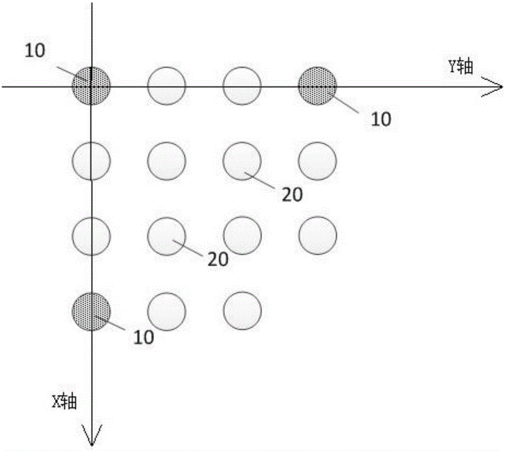
[0032] See figure 1 , in this embodiment, the road sign includes a coordinate label 10 and a coding label 20, and the coordinate label 10 and the coding label 20 are two labels with different functions in the road sign.

[0033] In this embodiment, an adhesive layer is provided on the back of the marks that make up the coordinate label 10 and the coded label 20; the marks are pasted on the ce...

no. 2 example

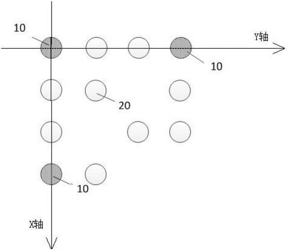
[0052] This embodiment provides a road sign for determining the position of the robot, please refer to figure 2 , the road sign includes coordinate labels 10 and coding labels 20 , two labels with different functions.

[0053] See figure 2 , in this embodiment, the coordinate label 10 is composed of three marks, with the mark at the middle position as the origin, and the other two marks are respectively located in the positive direction of the X axis and the Y axis centered on the origin. The three markings on the coordinate label 10 define the coordinate system of the signpost.

[0054] The coding label 20 is composed of nine marks, and the nine marks are distributed at different positions in the positive direction of the coordinate system. See figure 2 , according to the positive direction of the X-axis, in each row of marks, the number of marks constituting the coding label 20 is 2, 3, 3, 1 respectively. Through the coordinate system, the unique coordinates of the ni...

no. 3 example

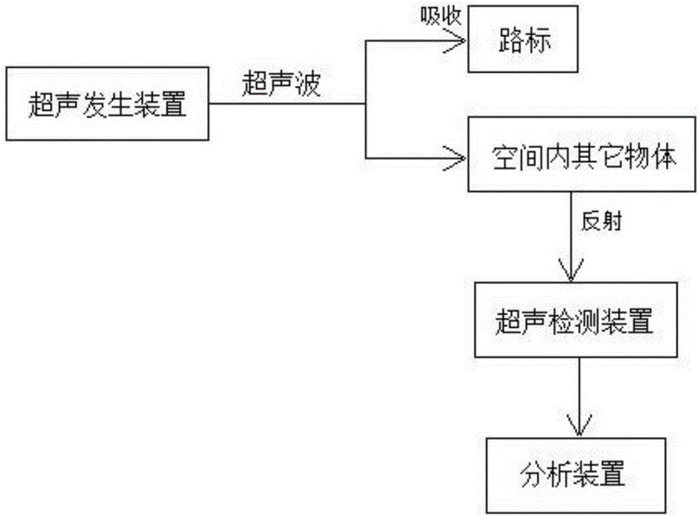
[0057] See image 3 , the present embodiment provides a device for determining the position of a robot, including the landmark described in any one of the first embodiment and the second embodiment, and also including an ultrasonic generating device, an ultrasonic detecting device and an analyzing device.

[0058] The road signs are arranged on the ceiling of the space where the robot is located, and the ultrasonic generating device, ultrasonic detecting device and analyzing device are arranged on the robot.

[0059] The ultrasonic generating device generates ultrasonic waves, and radiates the ultrasonic waves to road signs and other objects in the space where the robot is located. Since the road signs are made of ultrasonic-absorbing materials, the ultrasonic waves radiated to the road signs will be absorbed, while the ultrasonic waves radiated to other objects in the space will be reflected back.

[0060] The ultrasonic detection device detects the reflected ultrasonic wave...


PUM


Abstract

The invention provides a road sign and a device used for determining the position of a robot, wherein the road sign consists of one or more labels with different functions; each label consists of one or more signs; materials capable of absorbing ultrasonic waves are coated on the labels or the signs are made of the materials. According to the road sign provided by the invention, ultrasonic waves are applied to the road sign for determining the position of the robot, so that the ultrasonic wave radiation range is wide; the ultrasonic waves generated by the device provided by the invention can be radiated to the road sign and other objects of a space where the robot is located, so that all labels of the space where the robot is located can be detected once. The road sign is free of light interference and is high in recognition precision, so that road sign recognition efficiency is greatly improved.

Description

technical field [0001] The invention relates to the field of robots, in particular to a road mark and a device for determining the position of a robot. Background technique [0002] When a robot moves in space, it needs to confirm its position for path planning. The commonly used method to determine the position of a robot is to use artificial landmarks for position confirmation. [0003] Among the existing artificial road sign designs, there are artificial road signs designed with patterns with special color information or texture structure information, and artificial road signs designed with numbers, letters, two-dimensional codes or barcodes. However, the existing artificial road signs are usually captured by cameras, which are easily disturbed by external natural light. Moreover, in the prior art, the efficiency of using light reflection to identify road signs is relatively low. Contents of the invention [0004] The purpose of the present invention is to solve the d...

Claims


Application Information

Patent Timeline
Patent Type & Authority Applications(China)
IPC IPC(8): B25J19/02
CPCB25J19/02
Inventor 乔徽张腾飞何昭文
Owner HIT ROBOT GRP SHANGHAI CO LTD
Why Eureka
Try Eureka