
Gear shifting device and automobile

A technology of shifting device and shifting lever, which is applied to control devices, vehicle parts, transportation and packaging, etc., can solve the problems of low shifting comfort of automobiles and unadjustable shifting force of shifting devices.

Active Publication Date: 2017-01-11
GREAT WALL MOTOR CO LTD
View PDF4 Cites 1 Cited by
  • Summary
  • Abstract
  • Description
  • Claims
  • Application Information

AI Technical Summary

Problems solved by technology

[0004] In view of this, the present invention aims to propose a shifting device to solve the problem of low shifting comfort of an automobile due to the non-adjustable shifting force of the shifting device

Method used


Image

  • Gear shifting device and automobile
  • Gear shifting device and automobile
  • Gear shifting device and automobile

Examples


Embodiment 1

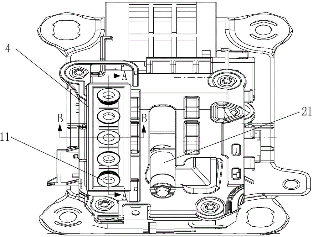
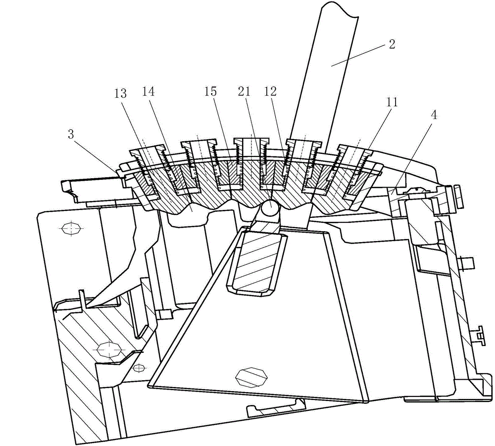
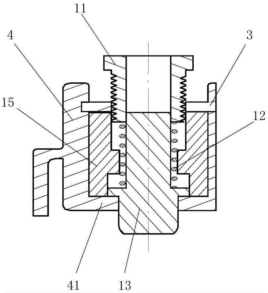
[0039] see figure 1 , the embodiment of the present invention provides a gear shifting device, including: a gear shift housing 4 having a housing chamber, and a gear shift lever 2 installed in the housing chamber of the gear shift housing 4, a fixed gear lever 21 and a gear shifter The positioning assembly, wherein the shift lever 2 protrudes from the shift housing 4, the fixed gear lever 21 is fixedly connected with the shift lever 2, the shift positioning assembly is located beside the fixed gear lever 21, and the shift positioning assembly includes a plurality of shift positioning components. Block 13, the bottom surface of each shift positioning block 13 is a protruding arc surface respectively, a shift positioning groove 14 is formed between two adjacent shift positioning blocks 13, when the shifting action is not performed, the fixed gear lever 21 The head is located in one of the shift positioning grooves 14, and an adjustment member is respectively arranged in the area...

Embodiment 2

[0051] Embodiment 2 of the present invention provides an automobile, which is provided with the shifting device provided in Embodiment 1 above. In the process of using the shifting device in the above-mentioned automobile, if a user with greater strength uses the above-mentioned shifting device, it is necessary to adjust the shifting device to increase the required shifting force to meet the requirements of the stronger user on the shifting force. Specifically, adjust the position of the adjusting member to increase the compression amount of the elastic member 12, so that the thrust force applied by the elastic member 12 to the shift positioning block 13 increases. During the shifting process, the shift lever 2 drives the fixed The force required for the shift rod 21 to push the shift positioning block 13 increases, thereby increasing the shift force; if the user with less strength uses the above shift device, the shift device needs to be adjusted to reduce the required shift f...


PUM


Abstract

The invention provides a gear shifting device and an automobile, and relates to the technical field of automobiles. The problem that the gear shifting comfort of the automobile is low is solved. The gear shifting device comprises a gear shifting shell body, a gear shifting rod, a gear fixing rod and a gear shifting positioning assembly, wherein the gear shifting shell body is provided with a containing cavity; the gear shifting rod is arranged in the gear shifting shell body, and one end of the gear shifting rod stretches out of the gear shifting shell body; the gear fixing rod and the gear shifting positioning assembly are arranged in the containing cavity; the gear fixing rod is fixedly connected with the gear shifting rod; the gear shifting positioning assembly comprises a plurality of gear shifting positioning blocks arranged in the gear shifting direction; a gear shifting positioning groove is formed between every two adjacent gear shifting positioning blocks; an adjusting piece of which one end stretches out of the gear shifting shell body is arranged in the area, corresponding to each gear shifting positioning block, in the gear shifting shell body; an elastic piece is arranged between each gear shifting positioning block and the corresponding adjusting piece; the two ends of the elastic pieces make contact with the gear shifting positioning blocks and the adjusting pieces correspondingly; and the positions of the adjusting pieces are adjusted, so that the compression amount of the elastic pieces is changed, and the gear shifting force is changed. The gear shifting device is used for improving the gear shifting comfort of the automobile.

Description

technical field [0001] The invention relates to the technical field of automobiles, in particular to a shifting device and an automobile. Background technique [0002] At present, the shifting device in an automobile usually includes: a shift lever, a fixed gear lever connected with the gear lever, and a positioning piece arranged above the fixed gear lever. The positioning piece is provided with a plurality of toothed grooves, each tooth shape The positions of the slots correspond to different gear positions respectively, and a spring is arranged between the fixed gear lever and the shift lever. In the process of shifting gears, the driver pushes the shift lever, and the shift lever drives the head of the fixed gear lever to move along the contour surface of the toothed groove, and the head of the fixed gear lever moves along the contour surface of the toothed groove. During the process, the compression amount of the spring is changed to ensure that the head of the stop ro...

Claims


Application Information

Patent Timeline
Patent Type & Authority Applications(China)
IPC IPC(8): B60K20/02
Inventor 罗聪聪段丽霞闫壮壮王中玉
Owner GREAT WALL MOTOR CO LTD
Learn More