Cylinder, compression mechanism, rotary compressor and heat pump device

A rotary compressor and compression mechanism technology, applied in the field of compressors, can solve the problems of low efficiency of rotary compression chamber, high cost of rotary compression chamber, high cost, etc., and achieve compact structure, reduced volume and weight, The effect of reducing the number of parts

Pending Publication Date: 2020-04-07
GUANGDONG MEIZHI PRECISION MFG
View PDF0 Cites 4 Cited by
  • Summary
  • Abstract
  • Description
  • Claims
  • Application Information

AI Technical Summary

Problems solved by technology

However, this design structure easily leads to two main problems. The first is that the cost of the increased rotary compression chamber is too high, and the cost of a series of corresponding structures remains high; the second is that the efficiency of the increased rotary compression chamber is low

Method used


Image

  • Cylinder, compression mechanism, rotary compressor and heat pump device
  • Cylinder, compression mechanism, rotary compressor and heat pump device
  • Cylinder, compression mechanism, rotary compressor and heat pump device

Examples


Embodiment Construction

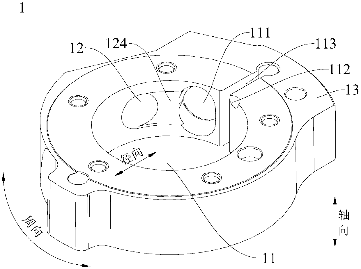
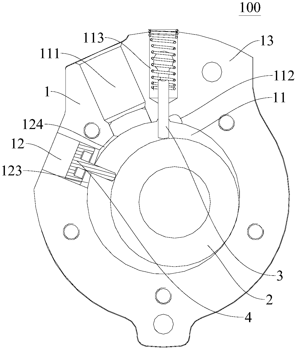
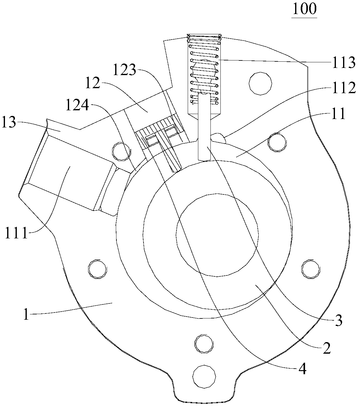
[0038] Embodiments of the present invention are described in detail below, examples of which are shown in the drawings, wherein the same or similar reference numerals designate the same or similar elements or elements having the same or similar functions throughout. The embodiments described below by referring to the figures are exemplary only for explaining the present invention and should not be construed as limiting the present invention.

[0039] In describing the present invention, it is to be understood that the terms "center", "vertical", "depth", "width", "upper", "lower", "vertical", "horizontal", "top" , "bottom", "inner", "outer", "counterclockwise", "axial", "radial", "circumferential", etc. indicate the orientation or positional relationship based on the orientation or positional relationship shown in the drawings , is only for the convenience of describing the present invention and simplifying the description, but does not indicate or imply that the referred devi...


PUM

PropertyMeasurementUnit
Depthaaaaaaaaaa

Abstract

The invention discloses a cylinder, a compression mechanism, a rotary compressor and a heat pump device. A compression cavity for rolling fit of a roller is defined in the cylinder, a sliding sheet groove and a first air suction port, both facing an opening of the compression cavity are formed in the circumferential wall of the cylinder, a piston cavity is defined in the circumferential wall of the cylinder, and the piston cavity is provided with a communication port formed in the inner circumferential surface of the compression cavity. According to the cylinder, the air discharge amount increasing mode of the cylinder can reduce the number of parts of the compressor, reduce the size and the weight, and greatly reduce the cost.

Description

technical field [0001] The invention relates to the field of compressors, in particular to a cylinder, a compression mechanism, a rotary compressor and a heat pump device. Background technique [0002] At present, there are technologies such as two-stage compression, multi-stage compression, independent compression, and variable volume compression in the air-conditioning industry. Design and match to achieve the above technical goals. However, this design structure easily leads to two main problems. The first is that the cost of the increased rotary compression chamber is too high, and the cost of a series of corresponding structures remains high; the second is that the efficiency of the increased rotary compression chamber is low . Contents of the invention [0003] The present invention aims to solve at least one of the technical problems existing in the prior art. For this reason, the present invention proposes a cylinder of a rotary compressor, which can add a pisto...

Claims


Application Information

Patent Timeline
IPC IPC(8): F04C29/00F04C29/12F04C18/356F25B1/04F25B31/00
CPCF04C18/3562F04C29/00F04C29/12F04C2240/10F04C2240/20F25B1/04F25B31/00
Inventor 吴延平林少坤宋鹏杰曹培森
Owner GUANGDONG MEIZHI PRECISION MFG
Why Eureka
Try Eureka