
Efficient film laminating machine

A laminator and high-efficiency technology, applied in packaging and other directions, can solve the problems of inability to accurately adjust the speed, reduce the working efficiency of the laminator, reduce the applicability of the laminator, etc., to improve the lamination effect, easy to promote, simple structure

Inactive Publication Date: 2017-01-11
王剑
View PDF5 Cites 3 Cited by
  • Summary
  • Abstract
  • Description
  • Claims
  • Application Information

AI Technical Summary

Problems solved by technology

[0002] Nowadays, with the development of science and technology, the development of mechanical technology is getting faster and faster, and the development of laminating machines has also attracted much attention, because many products need to be coated when they are produced, which can ensure the preservation of products The time is longer, and the safety of the product can be guaranteed, so sometimes the requirements for product lamination are relatively high, but the traditional laminating machine cannot meet the needs of modern society
[0003] Moreover, the traditional laminating machine is not easy to move, and the speed cannot be adjusted accurately during automatic laminating, which will greatly reduce the applicability of the laminating machine, and when the traditional laminating machine is laminating the product, Can not cover the product well, which greatly reduces the working efficiency of the laminating machine

Method used


Image

  • Efficient film laminating machine
  • Efficient film laminating machine

Examples


Embodiment

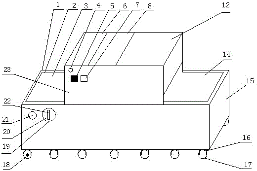
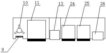
[0018] Example: see Figure 1-2 , a high-efficiency laminating machine of the present invention includes a laminating machine body 1, the laminating machine body 1 includes a working chamber 23 and a machine base 15, the working room 23 is fixedly connected to the machine base 15, and the working room 23 The main opening key 5 is provided on the top, the main opening key 5 is provided with a main key 7 on one side, the power indicator light 4 is provided on the one side of the working room 23, and the film coating chamber 6 is provided on the working room 23, so One side of the film coating chamber 6 is fixedly connected to the drying chamber 8, and one side of the drying chamber 8 is provided with a hot-press chamber 12, and the base 15 is provided with a conveyor belt 3, and the base 15 is provided with a transfer switch 21. One side of the transmission switch 21 is provided with a speed regulator 22, the speed regulator 22 is provided with a speed dial 20, the speed dial 20...


PUM


Abstract

The invention belongs to the technical field of film laminating machine equipment, and discloses an efficient film laminating machine. The efficient film laminating machine comprises a film laminating machine body. The film laminating machine body comprises a work room and a machine base. The work room is fixedly connected with the machine base and provided with a master opening key. One side of the master opening key is provided with a master closing key. One side of the work room is provided with a power source indicating lamp. The work room is provided with a film laminating room. A drying room is fixedly connected with one side of the film laminating room. A hot-pressing room is arranged on one side of the drying room. The machine base is provided with a conveying belt and a conveying switch. One side of the conveying switch is provided with a rotating speed adjuster. The rotating speed adjuster is provided with a rotating speed dial plate. The rotating speed dial plate is provided with a rotating speed adjusting rotary knob. One side of the machine base is provided with a feeding table. The other side of the machine base is provided with a discharging table. A foundation of the machine base is provided with multiple supporting feet. One side of each supporting foot is fixedly connected with a rolling wheel. By means of the rolling wheels at the bottom of the machine base, the device can be easily moved.

Description

technical field [0001] The invention relates to a laminating machine, in particular to a high-efficiency laminating machine, which belongs to the technical field of laminating machine equipment. Background technique [0002] Nowadays, with the development of science and technology, the development of mechanical technology is getting faster and faster, and the development of laminating machines has also attracted much attention, because many products need to be coated when they are produced, which can ensure the preservation of products The time is longer and the safety of the product can be guaranteed, so sometimes the requirements for product lamination are relatively high, but the traditional laminating machine cannot meet the needs of modern society. [0003] Moreover, the traditional laminating machine is not easy to move, and the speed cannot be adjusted accurately during automatic laminating, which will greatly reduce the applicability of the laminating machine, and wh...

Claims


Application Information

Patent Timeline
Patent Type & Authority Applications(China)
IPC IPC(8): B65B33/02
CPCB65B33/02
Inventor 王建
Owner 王剑
Learn More