Reinforced hydraulic buffer device

A hydraulic buffer and reinforcement technology, applied in the direction of shock absorbers, springs, springs/shock absorbers, etc., can solve the problems of device scrapping, waste of resources, and inability to ensure the sealing performance of the buffer device, so as to reduce the possibility of problems, The effect of saving resources

Active Publication Date: 2018-06-05
青岛科丰源塑料机械有限公司
View PDF6 Cites 0 Cited by
  • Summary
  • Abstract
  • Description
  • Claims
  • Application Information

AI Technical Summary

Problems solved by technology

At the same time, the hydraulic buffer device needs to be absolutely sealed, but after a long time of use, if there is a problem with any part, it will affect the sealing performance of the entire device. If the sealing performance cannot be guaranteed, the entire device will no longer have a buffering effect, resulting in the scrapping of the entire device. Under normal circumstances, the buffer device is directly fixed to the corresponding place, but when fixed, the force acts directly on the device, which is easy to cause pressure on the device itself, which is likely to cause deformation of the device. If deformation occurs, the original sealing There are likely to be gaps between good parts, and the gaps will not guarantee the sealing of the buffer device, resulting in the scrapping of the device and a waste of resources

Method used


Image

  • Reinforced hydraulic buffer device
  • Reinforced hydraulic buffer device

Examples


Embodiment Construction

[0013] The present invention will be further described below in conjunction with the accompanying drawings.

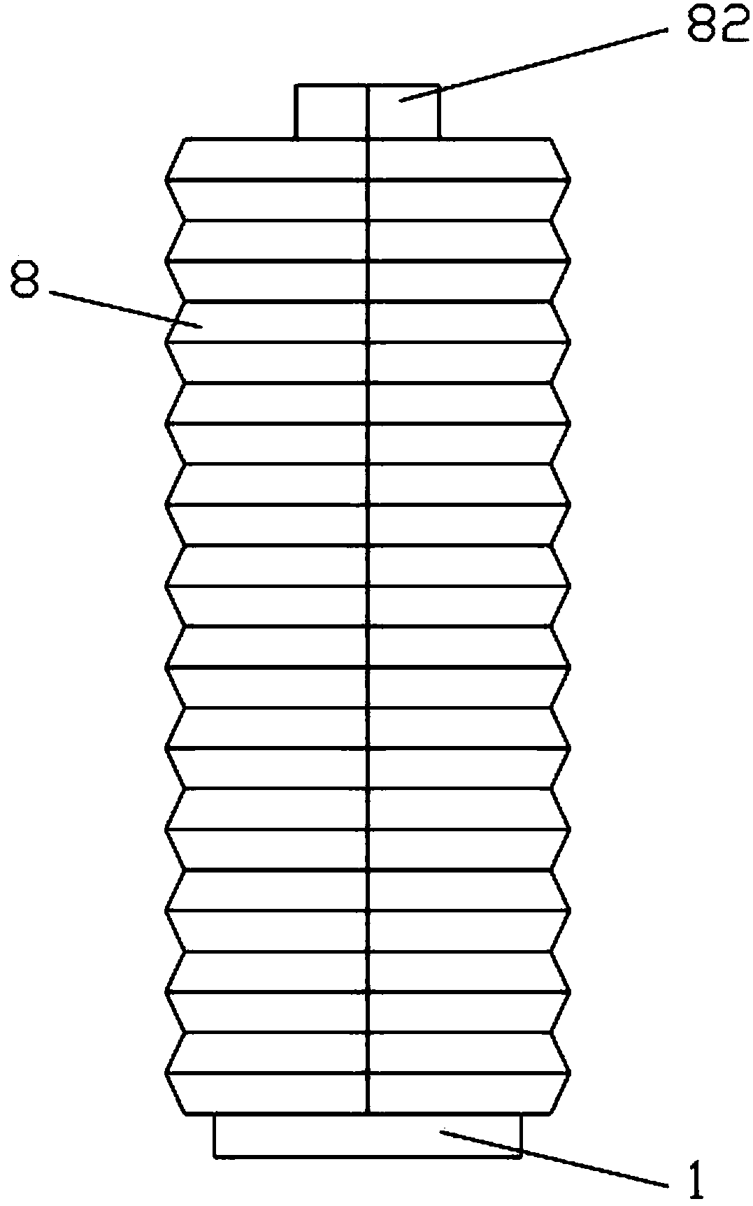
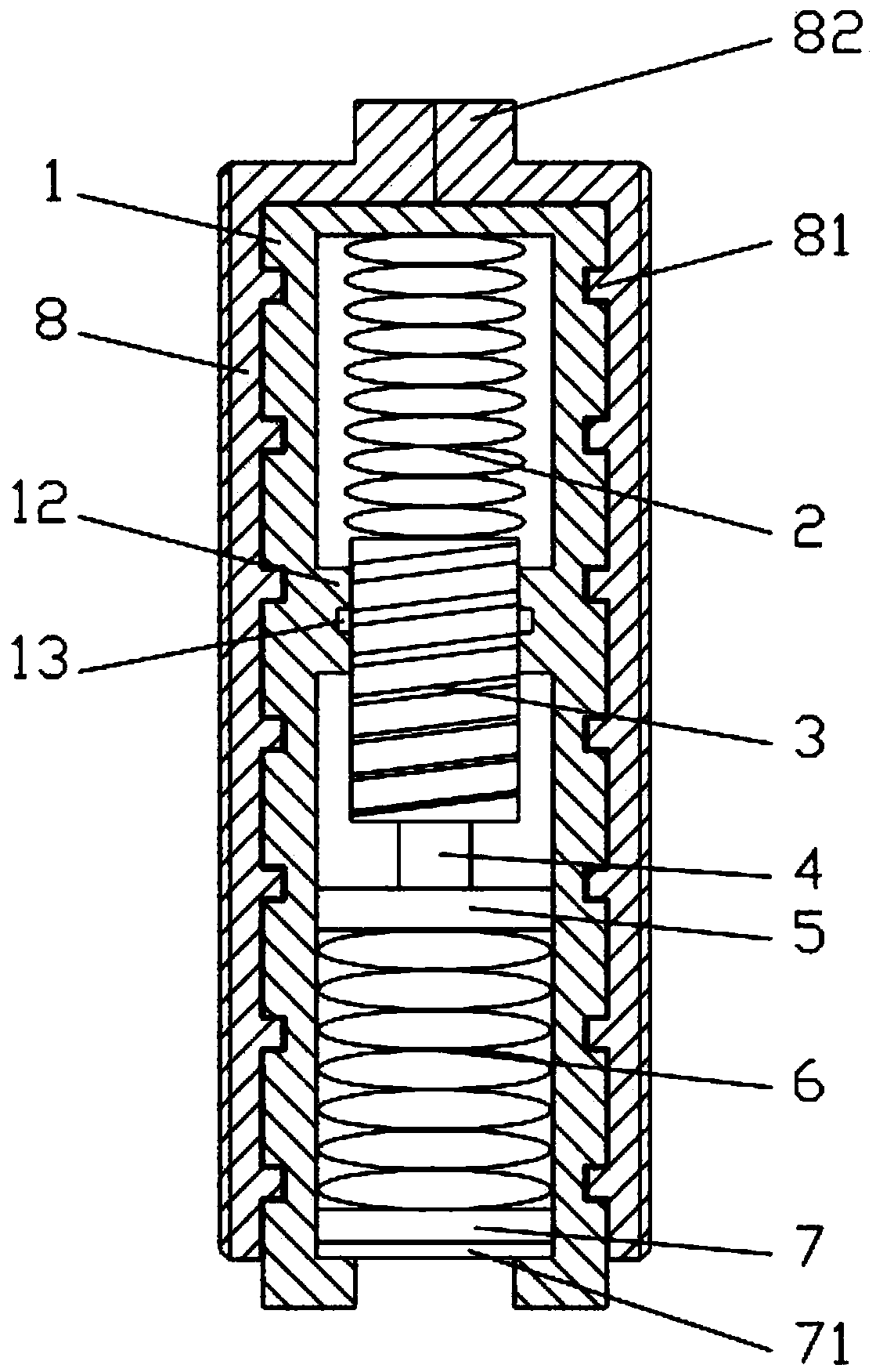
[0014] like figure 1 and figure 2 As shown, a reinforced hydraulic buffer device includes a core body 1, a casing 8 is sheathed outside the core body, a slot is provided on the outer surface of the core body 1, and a slot is provided on the inner surface of the casing 8 to match the shape of the slot. The protrusion 81 is stuck in the card slot, and the top of the housing 8 is fixed with a hexagonal nut 82, which is used to rotate the present invention into the corresponding place for fixing with a wrench. The housing 8 is divided into Two parts are convenient for installing the core body 1 in the housing 8. One end of the core body 1 is a closed end, and the other end is an open end, and the open end is connected to parts that need to be buffered on the machine.

[0015] A spiral groove piston 3 and an oil seal 5 are arranged inside the core body 1, and a first oil...


PUM


Abstract

Disclosed is a reinforced hydraulic buffer. The reinforced hydraulic buffer comprises a core, the outer part of the core is provided with a shell, the outer surface of the core is provided with a slot, the inner surface of the shell is provided with a protrusion matching the shape of the slot, a hexagonal nut is fixedly arranged at the top of the shell, the shell is divided by half into two parts in the longitudinal direction, and a first oil storage space is formed between the closed end of the core and a spiral groove piston. A second oil storage space is formed between the spiral groove piston and an oil seal. The spiral groove piston is provided with a spiral groove, the core is fixedly provided with an oil passage portion inside, the oil passage portion is provided with an annular groove, and the first oil storage space and the second oil storage space communicate with each other only through the gap formed by the annular groove and the spiral groove. The reinforced hydraulic buffer has the characteristics of reinforcement, and the force at the time of installation is applied to the shell that does not affect the sealing property of the entire device. Even if a certain deformation occurs, the sealing performance of the device is not greatly affected, the possibility of problem occurrence is greatly reduced, and resources are saved.

Description

technical field [0001] The invention relates to a hydraulic buffer device, in particular to a reinforced hydraulic buffer device. Background technique [0002] The hydraulic buffer device relies on hydraulic damping to buffer and decelerate the objects acting on it to a stop, which plays a certain degree of protection. It is suitable for mechanical equipment such as lifting transportation, elevators, metallurgy, port machinery, railway vehicles, etc. It is used as a safety buffer device to prevent mechanical damage caused by hard collisions during work. At the same time, the hydraulic buffer device needs to be absolutely sealed, but after a long time of use, if there is a problem with any part, it will affect the sealing performance of the entire device. If the sealing performance cannot be guaranteed, the entire device will no longer have a buffering effect, resulting in the scrapping of the entire device. Under normal circumstances, the buffer device is directly fixed to ...

Claims


Application Information

Patent Timeline
Patent Type & Authority Patents(China)
IPC IPC(8): F16F13/00F16F13/06F16F9/34
CPCF16F9/3405F16F13/007F16F13/06
Inventor 韩瑞成
Owner 青岛科丰源塑料机械有限公司
Why Eureka
Try Eureka