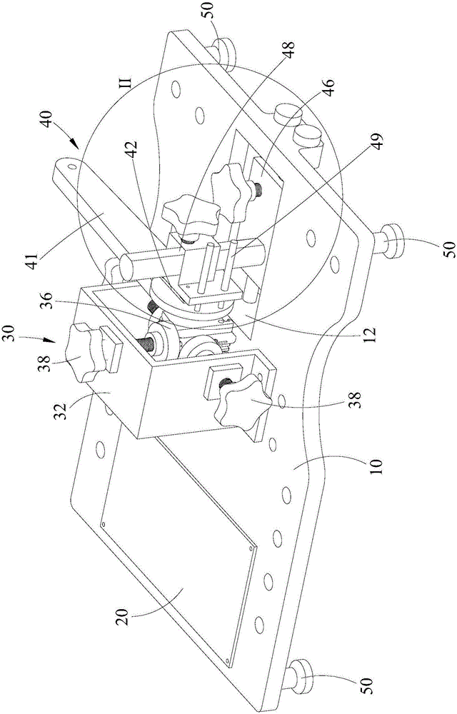
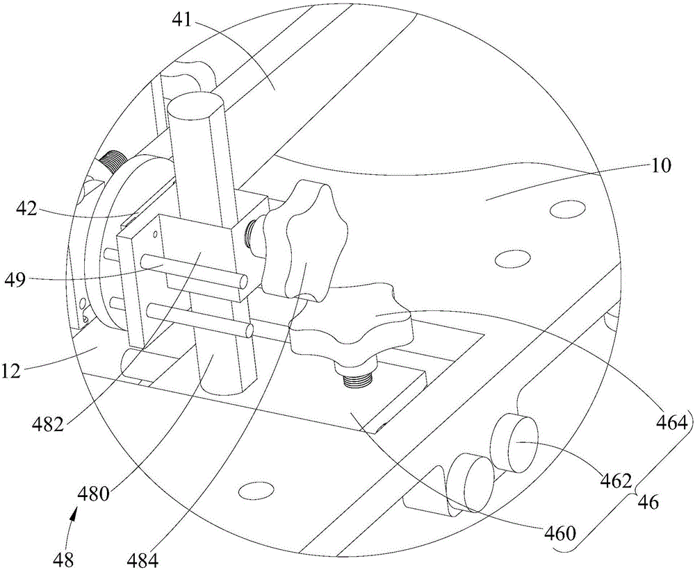
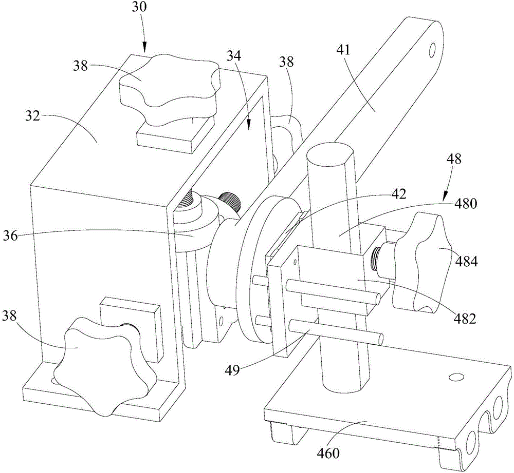
Virtual displacement tester for measuring virtual displacement of reduction gear unit

The technology of a reduction gear set and tester is applied in the field of virtual position tester, which can solve the problems of unable to measure the virtual position of reduction gears, and achieve the effect of simple operation and convenient use

Active Publication Date: 2017-01-11
UBTECH ROBOTICS CORP LTD
View PDF2 Cites 3 Cited by
  • Summary
  • Abstract
  • Description
  • Claims
  • Application Information

AI Technical Summary

Problems solved by technology

[0004] The purpose of the present invention is to provide a virtual position tester for measuring the virtual position of the reduction gear set, aiming to solve the technical problem that the reduction gear cannot be measured for the virtual position in the prior art

Method used


Image

  • Virtual displacement tester for measuring virtual displacement of reduction gear unit
  • Virtual displacement tester for measuring virtual displacement of reduction gear unit
  • Virtual displacement tester for measuring virtual displacement of reduction gear unit

Examples


Embodiment Construction

[0029] Embodiments of the present invention are described in detail below, examples of which are shown in the drawings, wherein the same or similar reference numerals designate the same or similar elements or elements having the same or similar functions throughout. The embodiments described below by referring to the figures are exemplary and are intended to explain the present invention and should not be construed as limiting the present invention.

[0030] In describing the present invention, it should be understood that the terms "length", "width", "upper", "lower", "front", "rear", "left", "right", "vertical", The orientation or positional relationship indicated by "horizontal", "top", "bottom", "inner", "outer", etc. are based on the orientation or positional relationship shown in the drawings, and are only for the convenience of describing the present invention and simplifying the description, rather than Nothing indicating or implying that a referenced device or element...


PUM


Abstract

The invention is applicable to the technical field of measuring devices, and provides a virtual displacement tester for measuring virtual displacement of a reduction gear unit. The virtual displacement tester comprises a base, a main control board, a display screen, an adjusting mechanism and a bilateral adjusting component, the adjusting mechanism comprises a rudder arm, a magnetic ring, a sub-circuit board, an angle sensor, a horizontal adjusting component and a vertical adjusting component, the rudder arm is mounted on an output shaft, the angle sensor is opposite to the magnetic ring, and the angle change of the magnetic ring is detected by the aid of the angle sensor. According to the virtual displacement tester for measuring virtual displacement of the reduction gear unit, the magnetic ring is mounted on the rudder arm, the position of the angle sensor relative to the magnetic ring on the sub-circuit board is adjusted by the horizontal adjusting component, the vertical adjusting component and the bilateral adjusting component, so that the angle sensor is adjusted to be aligned to the magnetic ring, the aligning position of the angle sensor and the magnetic ring is kept, and the angle change of the magnetic ring is detected by the aid of the angle sensor to effectively test virtual displacement errors of the reduction gear unit.

Description

technical field [0001] The invention belongs to the technical field of measuring devices, in particular to a dummy position tester for measuring the dummy position of a reduction gear set. Background technique [0002] The steering gear mainly includes a DC motor, a reduction gear set, a control circuit board, an angle sensor (such as a potentiometer), etc. When the steering gear is working, the control circuit board receives the control signal from the signal line to control the rotation of the DC motor, and the DC motor drives a series of The reduction gear set is transmitted to the output steering wheel after deceleration. The output shaft of the steering gear is connected to the position feedback potentiometer. When the steering wheel rotates, the position feedback potentiometer is driven. The potentiometer will output a voltage signal to the control circuit board for feedback, and then the control circuit board determines the motor according to its position. The direct...

Claims


Application Information

Patent Timeline
Patent Type & Authority Applications(China)
IPC IPC(8): G01R31/34
CPCG01R31/34
Inventor 舒文泉李冠佑张礼富柳冬熊友军
Owner UBTECH ROBOTICS CORP LTD
Why Eureka
Try Eureka