Prefabricated-type flexible DC cable terminal stress cone structure

A flexible DC and cable termination technology, applied in the direction of cable termination, cable accessories, cable installation, etc., can solve the problem of no proposed design theory and design method, etc.

Active Publication Date: 2017-01-11
NANJING NARI GROUP CORP +3
View PDF2 Cites 5 Cited by
  • Summary
  • Abstract
  • Description
  • Claims
  • Application Information

AI Technical Summary

Problems solved by technology

In the existing structural design of flexible straight cable terminals, most of them adopt the structural design of AC terminals and make slight adjustments, and no specific design theory and design methods have been proposed.

Method used


Image

  • Prefabricated-type flexible DC cable terminal stress cone structure
  • Prefabricated-type flexible DC cable terminal stress cone structure
  • Prefabricated-type flexible DC cable terminal stress cone structure

Examples


Embodiment 1

[0087] Use rated voltage ±320kV prefabricated flexible straight cable terminal.

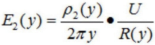
[0088] 1. The radial electric field intensity E at the stress cone curve y 2 (y) calculate

[0089] For ±320kV prefabricated flexible straight cable terminal, U=320kV; ρ 1,0 = ρ 2,0 =10 16 Ω.m; a 1 =0.06°C -1 , a 2 =0.05°C -1 ; θ c =90°C,w c =68W; ρ T1 =3.5K.m / W, ρ T2 =3.3K.m / W; r c = 26.5mm, R = 50.5mm; γ 1 = 2.2, γ 2 =1.69, bring the above data into the radial electric field intensity E at the stress cone curve y 2 (y) Calculation formula:

[0090] E = 7.29 × 10 14 × y 0.29 1.27 × 10 7 × ( E 2.28 × 10 ...

Embodiment 2

[0097] Adopt rated voltage ±200kV prefabricated flexible straight cable terminal.

[0098] 1. The radial electric field intensity E at the stress cone curve y 2 (y) calculate

[0099] For ±200kV prefabricated flexible straight cable terminals, U=200kV; ρ 1,0 = ρ 2,0 =10 16 Ω.m; a 1 =0.06°C -1 , a 2 =0.05°C -1 ; θ c =90°C,w c =66W; ρ T1 =3.5K.m / W, ρ T2 =3.3K.m / W; r c = 20.4mm, R = 36.4mm; γ 1 = 2.2, γ 2 =1.69, bring the above data into the radial electric field intensity E at the stress cone curve y 2 (y) Calculation formula:

[0100] E = 5.63 × 10 14 × y 0.27 8.47 × 10 6 × ( E 2.81 × 10 ...


PUM


Abstract

The invention provides a prefabricated-type flexible DC cable terminal stress cone structure, and the structure comprises a reinforcing insulation layer, a stress cone semiconducting layer, and a stress cone curve. The stress cone semiconducting layer is disposed on the insulating layer of a DC cable body. The reinforcing insulation layer is disposed on the stress cone semiconducting layer, and the stress cone curve is the lower edge of the stress cone semiconducting layer. On the basis of giving consideration to the impact on the resistivity from the temperature and an electric field, the invention proposes the distribution of an electric field in the insulation of a prefabricated-type flexible DC cable terminal, and provides a theoretical basis for the design of a flexible DC cable connection part. A method for calculating the thickness of the reinforcing insulation layer of the prefabricated-type flexible DC cable terminal is proposed, and guarantees that the interface electric field of the cable insulating layer and the reinforcing insulation layer is within a reasonable range. A reasonable stress cone is designed, thereby solving the phenomenon of centralized potential wires of the flexible DC cable terminal, and guaranteeing that the electric field of the whole stress cone is uniform. The structure meets the requirements of a whole flexible DC cable system for the electrical performances of the terminal, and guarantees the long-time safety and reliability of the flexible DC cable system.

Description

technical field [0001] The invention relates to a prefabricated flexible DC cable terminal stress cone structure. Background technique [0002] As a new type of power transmission, flexible direct current transmission has been paid more and more attention. The flexible DC cable system is an important part of the flexible direct transmission system, which consists of a flexible straight cable body and flexible straight cable connectors (joints and terminals). The flexible straight cable terminal is a key part of the cable system, and it is also a link that is more prone to failure, so it restricts the development of the flexible straight cable system to a higher voltage level. [0003] During cable termination design, the electric field distribution in the cable stress cone must be considered. In AC cable terminations, the electric field distribution depends on the dielectric constant of the insulating material and has nothing to do with the temperature distribution. In DC...

Claims


Application Information

Patent Timeline
Patent Type & Authority Applications(China)
IPC IPC(8): H02G15/02H02G1/14
CPCH02G1/14H02G15/02H02G15/064
Inventor 朱智恩杨黎明陈龙啸李栋
Owner NANJING NARI GROUP CORP
Why Eureka
Try Eureka