Solar panel stand

A solar panel and stand technology, applied in photovoltaic power generation, photovoltaic modules, electrical components, etc., can solve the problems of time and effort, and achieve the effect of reducing the number of parts and making it easier to set up operations.

Inactive Publication Date: 2017-01-11
NIKKEIKIN ALUMINUM CORE TECH +6
View PDF6 Cites 3 Cited by
  • Summary
  • Abstract
  • Description
  • Claims
  • Application Information

AI Technical Summary

Problems solved by technology

Therefore, the number of parts will increase, and there is a probl

Method used


Image

  • Solar panel stand
  • Solar panel stand
  • Solar panel stand

Examples


Example

[0035] (First embodiment)

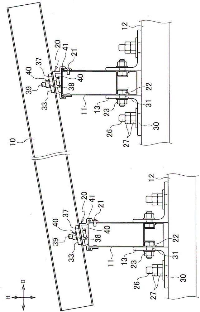
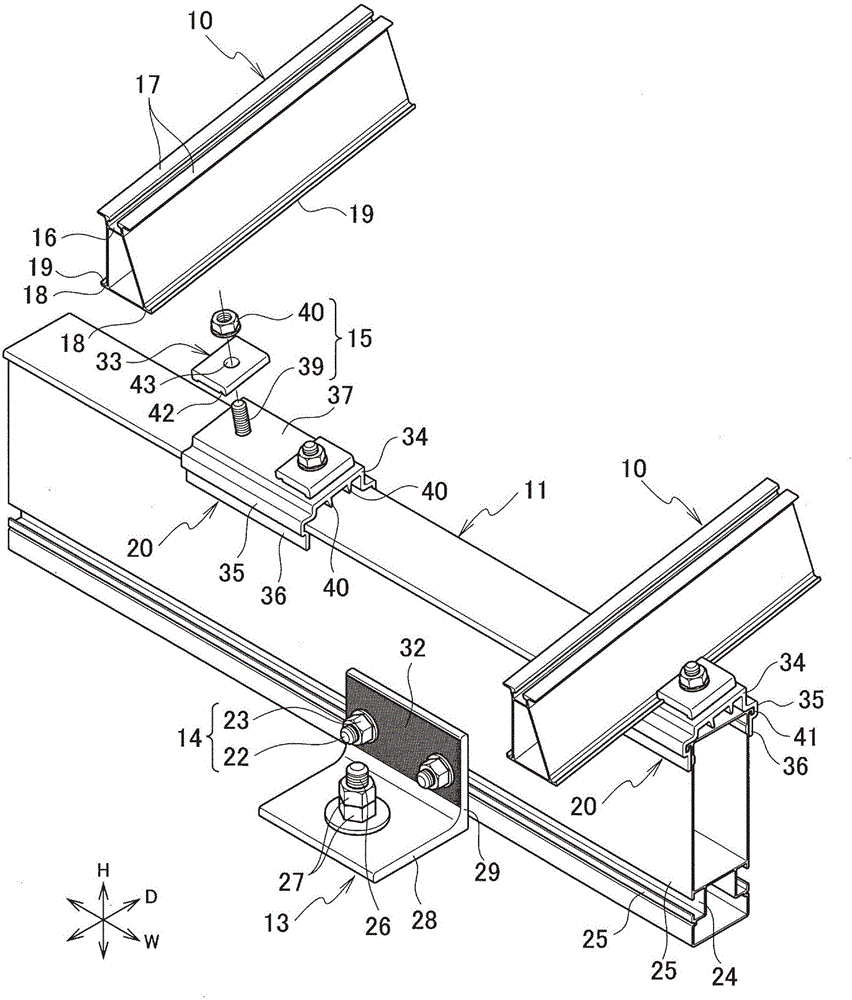
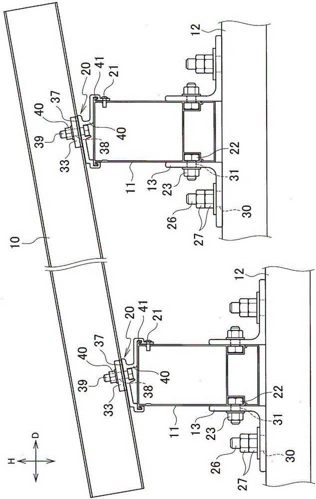
[0036] Such as figure 1 and figure 2 As shown, the solar mount of the first embodiment of the present invention has a first frame member (rafter) 10 that supports a solar panel (not shown); supports the first frame member 10 and crosses the first frame member 10 along A second frame member (rafter seat) 11 extending in the direction of, and a fixing member 13 fixed to the base 12 arranged on the installation surface. The second frame member 11 and the fixing member 13 are fixed via the fastening member 14, and the first frame member 10 and the second frame member 11 are fixed via the fastening member 15. In this embodiment, the first frame member 10 and the second frame member 11 are arranged orthogonally. In addition, the height of the base 12 is different at one side (front surface side) and the other side (rear surface side) of the depth direction D of the stand for solar panels. Specifically, the base 12 is installed so that the back surface sid...


PUM


Abstract

To provide a solar panel stand which has a small number of parts and can be easily installed. The stand for a solar panel comprises a first frame member 10 for supporting a solar panel, a second frame member 11 for supporting the first frame member 10 and extending in an orthogonal direction, and fixing members 13 fixed to the disposed foundation 12. The fixing member 13 is arranged in a pair so as to sandwich the second frame member 11 from both sides, and each fixing member 13 has a first fixing portion 29 fixed to the foundation 12 and a second fixing portion 28 that is fixed to the second frame member 11.

Description

technical field [0001] The present invention relates to a stand for a solar panel. Background technique [0002] Conventionally, a solar panel stand for installing a solar panel is known (for example, refer to Patent Document 1). In such a stand for a solar panel, a structure is generally provided in which a frame member supporting a solar panel is supported from below by a pillar. [0003] prior art literature [0004] patent documents [0005] Patent Document 1: Japanese Patent Laid-Open No. 2015-31078 [0006] In the stand for solar panels described in Patent Document 1, the frame member is supported by pillars fixed above the base, and braces for reinforcement are bridged between adjacent pillars. Therefore, the number of parts increases, and there is a problem that labor and time are required to install the solar panel stand. Contents of the invention [0007] Therefore, an object of the present invention is to provide a stand for a solar panel that can easily pe...

Claims


Application Information

Patent Timeline
IPC IPC(8): H02S30/10
CPCH02S30/10Y02E10/50
Inventor 斋藤荣德西本耐竹内孝之樋上博幸石川博光田川义孝小野猛永田刚丈古川宏典长尾隆史
Owner NIKKEIKIN ALUMINUM CORE TECH
Why Eureka
Try Eureka