Darlington structure microwave chaotic circuit and its chip, circuit module and design method

A chaotic circuit and microwave technology, which is used in secure communication through chaotic signals, electrical components, digital transmission systems, etc., can solve problems such as the reduction of the oscillation loop, the difficulty of breaking through the limits of the chaotic oscillation frequency and bandwidth, and achieve the improvement of spectrum bandwidth, negative The effect of resistance lifting

Active Publication Date: 2019-05-07
CHINA ELECTRONIC TECH GRP CORP NO 38 RES INST
View PDF3 Cites 0 Cited by
  • Summary
  • Abstract
  • Description
  • Claims
  • Application Information

AI Technical Summary

Problems solved by technology

[0004] This prior art Colpitts structure microwave chaotic circuit is simple and practical, but when the frequency rises, the negative resistance of the oscillation loop decreases with the decrease of the gain of transistor Q1, and the chaotic oscillation frequency and bandwidth are difficult to break through the limit

Method used


Image

  • Darlington structure microwave chaotic circuit and its chip, circuit module and design method
  • Darlington structure microwave chaotic circuit and its chip, circuit module and design method
  • Darlington structure microwave chaotic circuit and its chip, circuit module and design method

Examples


Embodiment Construction

[0042] The technical solutions in the embodiments of the present invention will be clearly and completely described below in conjunction with the accompanying drawings in the embodiments of the present invention. Obviously, the described embodiments are only part of the embodiments of the present invention, not all of them. Based on the embodiments of the present invention, all other embodiments obtained by persons of ordinary skill in the art without creative efforts fall within the protection scope of the present invention. The present invention will be described in further detail below in conjunction with examples and specific implementation methods.

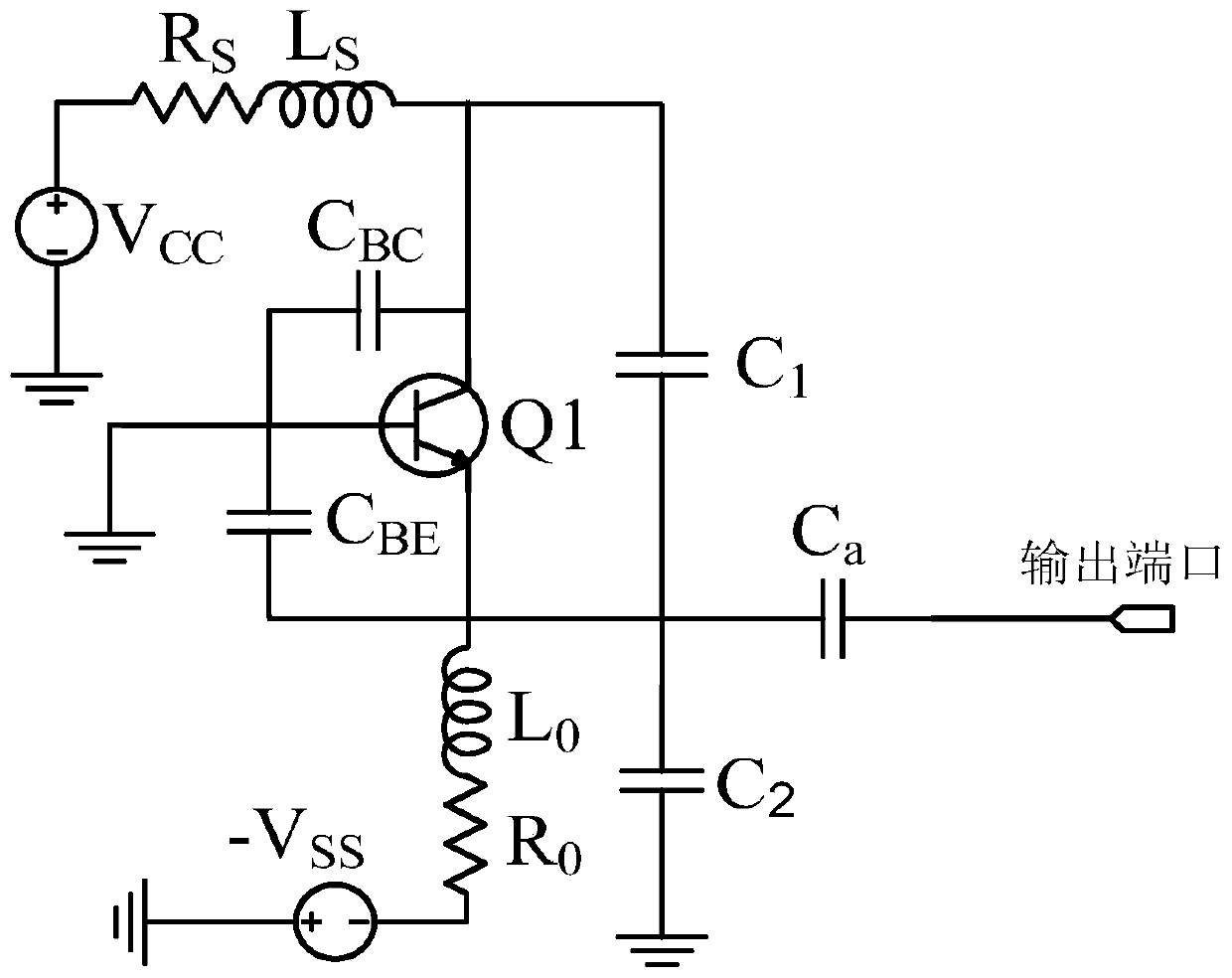
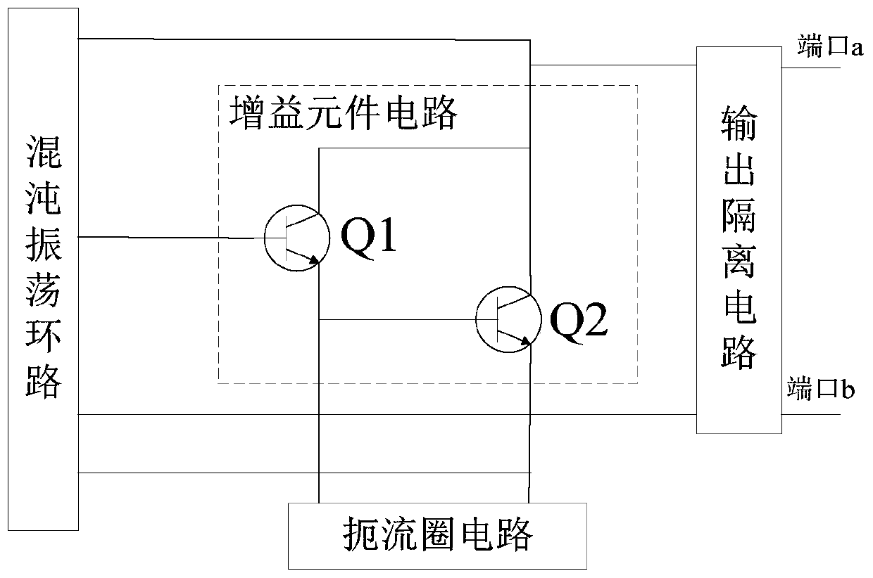
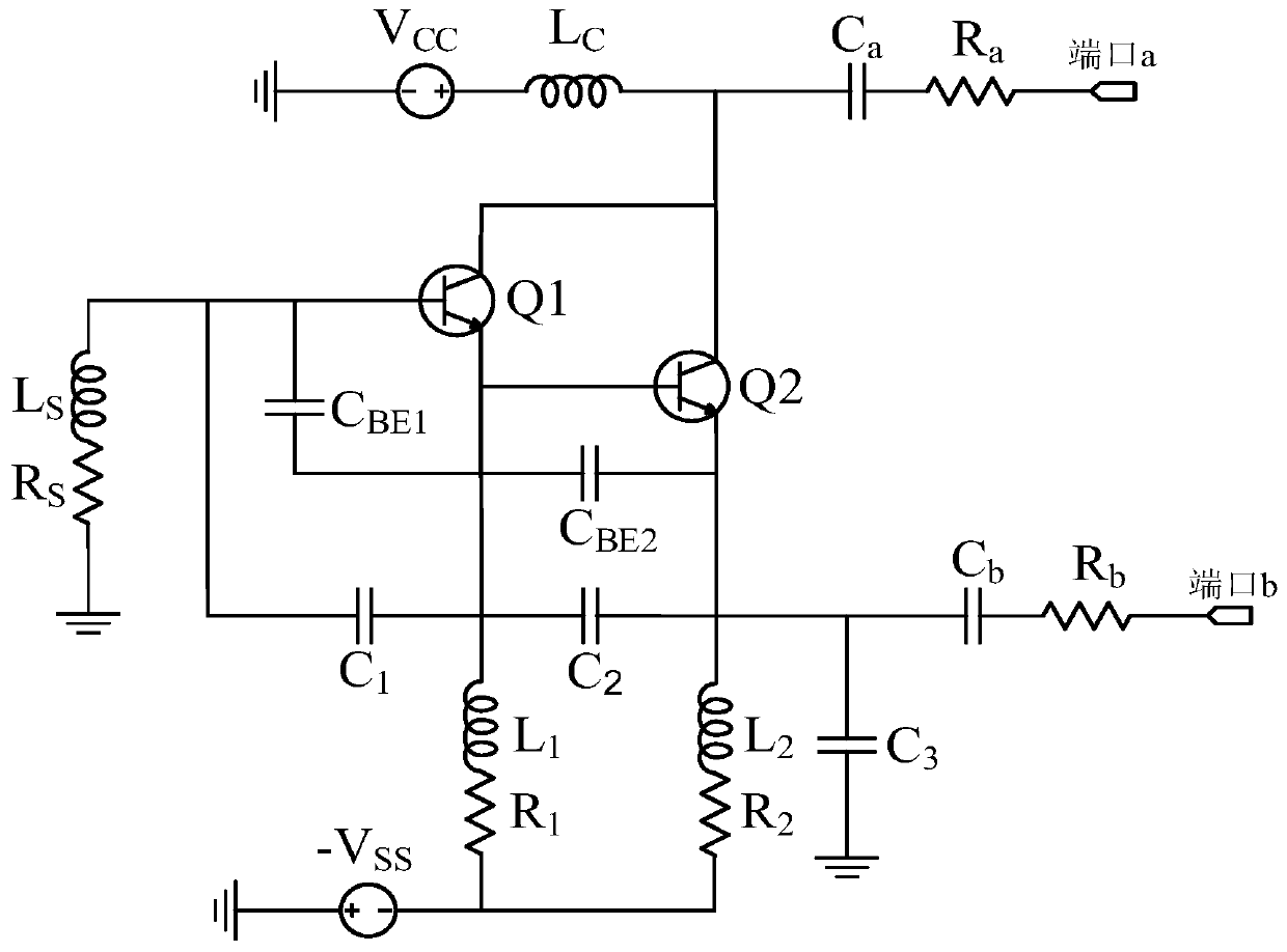
[0043] see figure 2 , The Darlington structure microwave chaotic circuit of the present invention includes a gain element circuit, a chaotic oscillation loop, a choke coil circuit, and an output isolation circuit. The gain element circuit uses a transistor Q 1 , Q 2 , Q 1 The emitter is connected to Q 2 bases of the two...


PUM


Abstract

The invention discloses a Darlington structure microwave chaotic circuit as well as a chip, circuit module and design method of the Darlington structure microwave chaotic circuit. The Darlington structure microwave chaotic circuit comprises a gain component circuit, a chaos oscillation loop, a choke ring circuit and an output isolation circuit; the gain component circuit is composed of two transistors Q1 and Q2; the emitter of Q1 is connected with the base of Q2; the two collectors of the two transistors Q1 and Q2 are connected; the two emitters of the two transistors Q1 and Q2 are connected; and the two connected collectors and the two connected emitters of the two transistors Q1 and Q2 are adopted as two independent output ports a and b of the Darlington structure microwave chaotic circuit respectively; the choke ring circuit is adopted as a constant current source bias circuit of the Darlington structure microwave chaotic circuit; one end of the choke ring circuit is connected with a negative voltage source -Vss, and the other end of the choke ring circuit is connected with the two emitters of the two transistors; the chaos oscillation loop is connected with the three poles of each transistor and is used for outputting chaotic signals to the gain component circuit; and the output isolation circuit isolates the two output ports a and b from the chaotic oscillation loop.

Description

technical field [0001] The present invention relates to a microwave chaotic circuit, in particular to a Darlington structure microwave chaotic circuit, a chip adopting the Darlington structure microwave chaotic circuit, a circuit module adopting the Darlington structure microwave chaotic circuit, the The design method of microwave chaotic circuit with Darlington structure is described. Background technique [0002] Because the chaotic signal has the characteristics of broadband, internal randomness, nonlinearity, and noise-like power spectrum, and the structure of the chaotic circuit is simple and easy to construct, the chaotic circuit is widely used in secure communication, broadband communication, spread spectrum communication, chaotic radar, electronic Confrontation and many other fields. The common structures of chaotic signal circuits include Wien bridge chaotic circuit, Chua's chaotic circuit and Colpitts chaotic circuit. The Wien bridge circuit and Chua's circuit ca...

Claims


Application Information

Patent Timeline
Patent Type & Authority Patents(China)
IPC IPC(8): H04L9/00
CPCH04L9/001
Inventor 陈文兰郑林华张德智陈阳宋晓侠
Owner CHINA ELECTRONIC TECH GRP CORP NO 38 RES INST
Why Eureka
Try Eureka