Speed reducer transmission efficiency test system

A technology of transmission efficiency and test system, which is applied in the direction of machine gear/transmission mechanism test, etc., can solve the problems of inaccuracy and universality of the reducer test system, and achieve the effects of convenient docking or separation, improved coaxiality, and convenient installation

Inactive Publication Date: 2017-01-18
ZHEJIANG SHUANGHUAN DRIVELINE
View PDF5 Cites 9 Cited by
  • Summary
  • Abstract
  • Description
  • Claims
  • Application Information

AI Technical Summary

Problems solved by technology

[0004] The present invention aims at the inaccurate and poor versatility of the reducer

Method used


Image

  • Speed reducer transmission efficiency test system
  • Speed reducer transmission efficiency test system
  • Speed reducer transmission efficiency test system

Examples


Embodiment 1

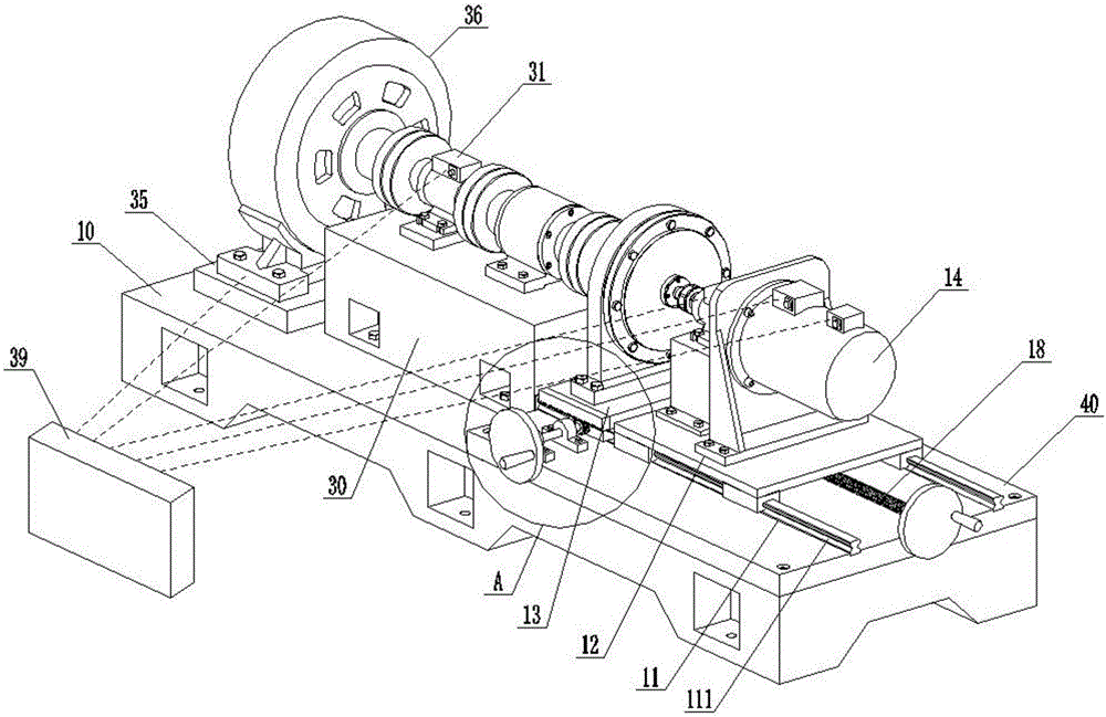
[0030] A transmission efficiency test system for a reducer, such as Figure 1-10As shown, including the base 10, the base 10 is provided with an anti-vibration pad 40, the anti-vibration pad 40 is fixedly connected with the base 10 by bolts, and at least one guide rail 11 is provided on the end surface of the anti-vibration pad 40, and the base 10 of this embodiment is provided with Two guide rails 11, rail grooves 111 are provided on both sides of the guide rail 11, a motor bracket 12 and a reducer bracket 13 are arranged on the guide rail 11, the motor bracket 12 and the reducer bracket 13 share the same guide rail 11, the motor bracket 12 and the reducer bracket 13 all slide on the guide rail 11, and the speed reducer tested in this embodiment is an RV speed reducer.

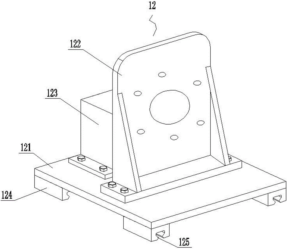
[0031] The motor bracket 12 includes a first moving plate 121 and a first supporting seat 122 fixed on the first moving plate 121. A motor 14 is fixed on the first supporting seat 122. The motor 14 is a varia...


PUM


Abstract

The invention relates to detection of speed reducer transmission efficiency and discloses a speed reducer transmission efficiency test system. The system comprises a base (10). The base (10) is provided with an anti-vibration pad (40); the end surface of the anti-vibration pad (40) is provided with at least one guide rail (11); the guide rail (11) is provided with a motor support (12) and a speed reducer support (13); and the motor support (12) and the speed reducer support (13) are slidably arranged on the guide rail (11). The system can detect different types of speed reducers; the motor support and the speed reducer support ate arranged independently to facilitate installation of the test system; the motor support can slide on the guide rail, thereby facilitating connection or separation of the motor output end and the speed reducer input end; the speed reducer support can slide on the guide rail, thereby facilitating connection or separation of the speed reducer output end; operating personnel are easy to operate; and the motor support and the speed reducer support share one guide rail, thereby improving coaxiality and facilitating ducking or separation of the components.

Description

technical field [0001] The invention relates to testing the transmission efficiency of a reducer, in particular to a test system for the transmission efficiency of a reducer. Background technique [0002] As the most important reducer for robot joints, the reducer has a series of advantages such as small size, light weight, large transmission ratio range, high carrying capacity, high precision, high efficiency, and stable transmission. The quality of its transmission performance directly affects the overall performance of industrial robots. [0003] With the continuous improvement of industrial production automation and precision, the demand for industrial robots is increasing rapidly. It is more and more important to develop and develop high-performance reducers. In the process of research and development and manufacturing of reducers, the transmission performance is tested to improve the design. , is one of the essential links. The transmission efficiency is an important...

Claims


Application Information

Patent Timeline
IPC IPC(8): G01M13/02
CPCG01M13/02
Inventor 张靖韩益南朱忠刚
Owner ZHEJIANG SHUANGHUAN DRIVELINE
Why Eureka
Try Eureka