
Real-time fault diagnosis method and device

A real-time fault, fault technology, applied in instrumentation, electrical testing/monitoring, control/regulation systems, etc.

Active Publication Date: 2017-01-18
清华大学苏州汽车研究院(吴江)
View PDF12 Cites 20 Cited by
  • Summary
  • Abstract
  • Description
  • Claims
  • Application Information

AI Technical Summary

Problems solved by technology

[0003] The purpose of the embodiment of the present invention is to propose a method and device for real-time fault diagnosis, aiming to solve the problem of how to detect the fault of pure electric vehicles in real time and maintain information interaction with the outside

Method used


Image

  • Real-time fault diagnosis method and device
  • Real-time fault diagnosis method and device
  • Real-time fault diagnosis method and device

Examples


Embodiment Construction

[0054] The embodiments of the present invention will be further described in detail below in conjunction with the drawings and embodiments. It should be understood that the specific embodiments described here are only used to explain the embodiments of the present invention, rather than to limit the embodiments of the present invention. In addition, it should be noted that, for the convenience of description, the drawings only show some but not all structures related to the embodiments of the present invention.

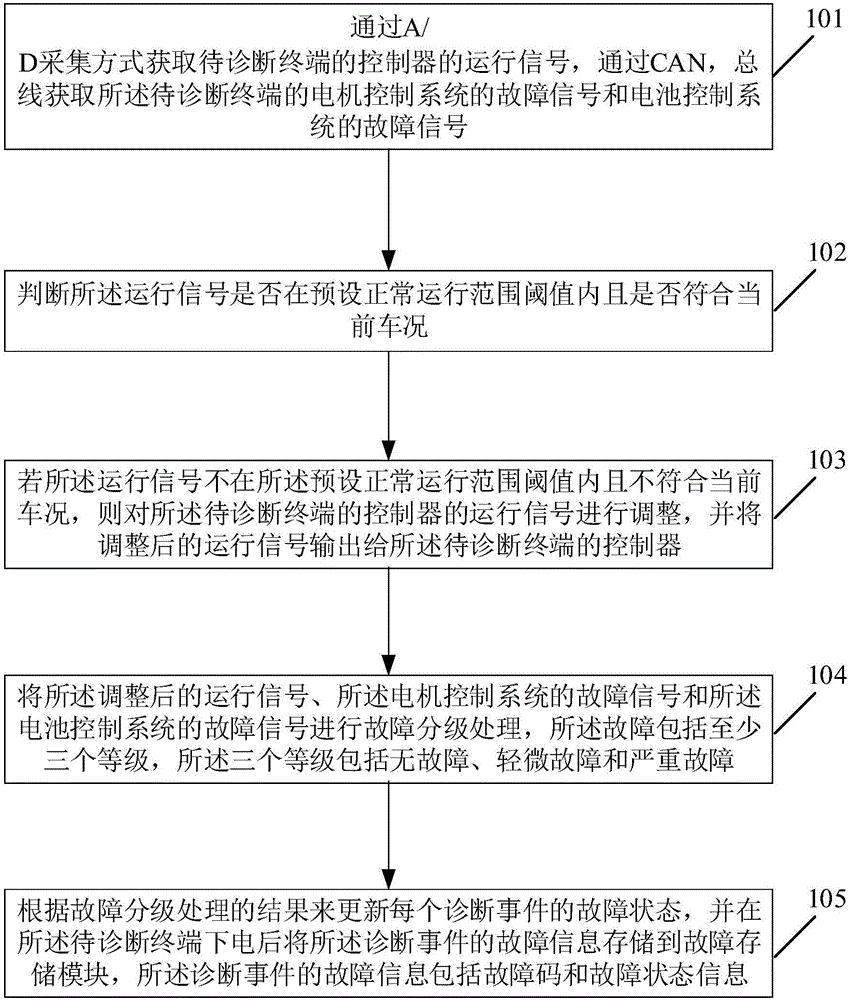
[0055] refer to figure 1 , figure 1 It is a schematic flowchart of a method for real-time fault diagnosis provided by an embodiment of the present invention.

[0056] Such as figure 1 Shown, the method for described real-time fault diagnosis comprises:

[0057]Step 101, acquire the operating signal of the controller of the terminal to be diagnosed through A / D acquisition, and acquire the fault signal of the motor control system and the fault signal of the battery ...


PUM


Abstract

The embodiment of the invention discloses a real-time fault diagnosis method and device. The method comprises the steps that an operating signal of a controller of a terminal to be diagnosed is acquired in an A / D acquisition mode, and a fault signal of a motor control system of the terminal to be diagnosed and a fault signal of a battery control system of the terminal to be diagnosed are acquired through a CAN bus; the adjusted operating signal, the fault signal of the motor control system and the fault signal of the battery control system are subjected to fault grading processing; the fault state of each diagnosis event is updated according to the fault grading processing result, fault information of the diagnosis events is stored in a fault storage module after the terminal to be diagnosed is powered off, and the fault information of the diagnosis events comprises fault codes and fault state information. Therefore, a self-diagnosis function, namely, a car-mounted diagnosis function, is set in an automobile control system; real-time diagnosis is carried out through diagnosis equipment in a car, and the diagnosis information is stored in a memorizer in the form of the fault codes.

Description

technical field [0001] Embodiments of the present invention relate to the technical field of pure electric vehicles, in particular to a method and device for real-time fault diagnosis. Background technique [0002] Pure electric vehicles run on electricity, so there are no emissions glitches. However, at the current stage, there are still malfunctions affecting vehicle safety and functions, so online diagnosis and recording are required. With the increasing electronicization of automobiles, the number of electronic control systems in automobiles continues to increase. In addition to the core components and vehicle controllers of pure electric vehicles, the fault status and operation status of the motor control system and battery control system also affect the function and safety of the car. . Therefore, in order to facilitate maintenance and monitoring, it is necessary to detect and diagnose the faults of pure electric vehicles in real time. Contents of the invention ...

Claims


Application Information

Patent Timeline
Patent Type & Authority Applications(China)
IPC IPC(8): G05B23/02
CPCG05B23/0213
Inventor 金达锋祁文静邓晓茜
Owner 清华大学苏州汽车研究院(吴江)
Learn More