Centrally-distributed coreless winding

A hollow cup and winding technology, applied in the field of winding, can solve problems such as inability to effectively use the back EMF, achieve the effects of preventing potential safety hazards, improving the back EMF, and being easy to implement in engineering

Active Publication Date: 2017-01-18
SHANGHAI MOONS ELECTRICAL APPLIANCE
View PDF5 Cites 8 Cited by
  • Summary
  • Abstract
  • Description
  • Claims
  • Application Information

AI Technical Summary

Problems solved by technology

For the conductor 2-2, the traditional winding method distributes the conductor 2-1 and the staggered conductor 2-2 evenly in 120° (including but not limited to 120°), but evenly distributes the staggered conductor in the winding , the back EMF generated by the staggered conductors cannot be effectively used, and the back EMF generated by the conductor far away from the winding center line is smaller than the back EMF generated by the conductor near the winding center line

Method used


Image

  • Centrally-distributed coreless winding
  • Centrally-distributed coreless winding
  • Centrally-distributed coreless winding

Examples


Embodiment

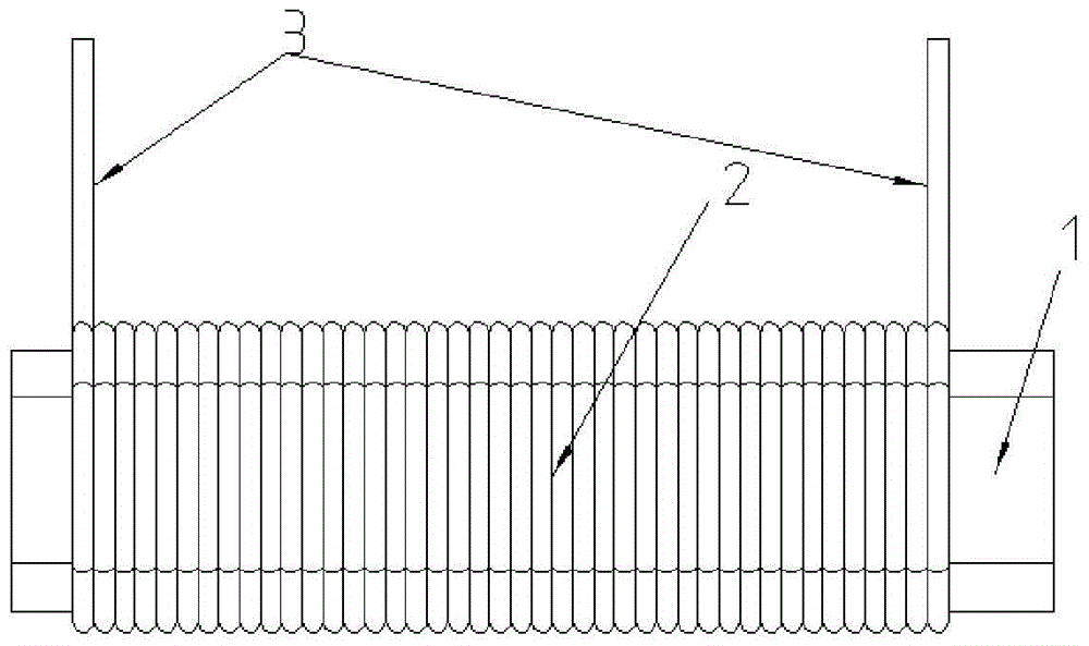
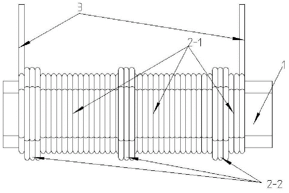
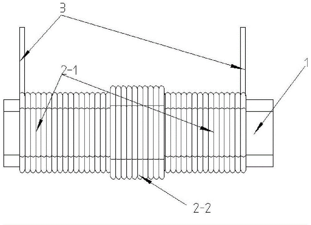
[0020] like image 3 As shown, a hollow cup winding with concentrated distribution includes a staggered conductor 2-2, a normal conductor 2-1 and a winding tap 3. The staggered conductor 2-2 is concentrated in the middle of the winding, and the normal The conductor 2-1 is distributed on both sides of the staggered conductor 2-2, the winding taps 3 are located at both ends of the normal conductor 2-1, and the conductor density of the middle part of the winding where the staggered conductor 2-2 is located is Greater than normal conductor 2-1.

[0021] The number of the staggered conductors 2-2 is 1 / 10 to 1 / 2 of that of the normal conductors 2-1. Preferably, the number of the staggered conductors 2-2 is 1 / 4 of that of the normal conductors 2-1.

[0022] The conductor density of the winding gradually decreases from the middle to both sides. The number of conductors of the staggered-layer conductor 2-2 is proportional to the inner diameter of the winding after winding.

[0023]...


PUM


Abstract

The invention relates to a centrally-distributed coreless winding, which comprises layer-staggered conductors, normal conductors and winding taps. The layer-staggered conductors are disposed in the middle position of the winding in a centralized manner, the normal conductors are distributed on two sides of the layer-staggered conductors, the winding taps are located on two end portions of the normal conductors, and the wire density of the middle part of the winding is higher than that of the normal conductors. Compared with the prior art, the centrally-distributed coreless winding effectively improves the counter potential of a coreless motor, and further enhances performance of the motor.

Description

technical field [0001] The invention relates to a winding, in particular to a centrally distributed hollow cup winding. Background technique [0002] In the traditional coreless motor winding process, the conductor 2 is generally wound evenly on the winding die 1, and the winding taps 3 are located at both ends of the coil, see figure 1 , after hot flattening and hot rounding, a hollow cup winding is formed. In this winding arrangement, since the conductors are evenly distributed in space within 120°, when the back EMF vector on the conductor is projected to the center line, the back EMF utilization rate of the vector near the center line is much greater than that of the vectors on both sides. [0003] When the number of series turns per phase of the coreless winding increases or the wire diameter becomes larger, due to the limited length of the winding die, the same layer of conductors cannot be wound on the space of one layer, so the position of the conductors will inevit...

Claims


Application Information

Patent Timeline
Patent Type & Authority Applications(China)
IPC IPC(8): H02K3/28
CPCH01F5/00H02K3/04H02K3/28
Inventor 金万兵唐斌松聂慧凡何欣
Owner SHANGHAI MOONS ELECTRICAL APPLIANCE
Why Eureka
Try Eureka