
A magnetism-concentrating stator permanent magnet vernier motor

A vernier motor, permanent magnet type technology, applied in the direction of magnetic circuit shape/style/structure, magnetic circuit static parts, etc., can solve the problems of small stator winding back EMF, large amount of permanent magnets, small magnetic density, etc., to achieve reverse The effect of increasing the potential, reducing the leakage flux of the teeth, and increasing the air gap flux density

Active Publication Date: 2016-01-20
CHANGSHU HUASEN TEXTILE
View PDF4 Cites 0 Cited by
  • Summary
  • Abstract
  • Description
  • Claims
  • Application Information

AI Technical Summary

Problems solved by technology

[0004] The purpose of the present invention is to propose a magnetism-concentrating type vernier motor in order to solve the problems of serious flux leakage, small magnetic density in the air gap, small counter electromotive force in the stator winding, and excessive permanent magnet consumption in the existing stator permanent magnet vernier motor. Stator permanent magnet vernier motor

Method used


Image

  • A magnetism-concentrating stator permanent magnet vernier motor
  • A magnetism-concentrating stator permanent magnet vernier motor
  • A magnetism-concentrating stator permanent magnet vernier motor

Examples


Embodiment Construction

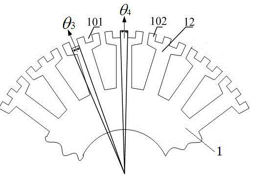
[0020] See figure 1 The present invention includes a coaxial stator 1 and a rotor 2, and the rotor 2 is located outside the stator 1. There is a slot 19 in the center of the stator 1 for placing the rotating shaft. There is an air gap between the rotor 2 and the stator 1, and the thickness of the air gap is selected according to the size and requirements of the motor. The stator 1 is composed of stator teeth 12 and stator slots 14, the stator slots 14 are used to place windings, and the tooth ends of the stator teeth 12 are embedded with permanent magnet units 300.

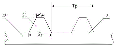
[0021] For the specific structure and proportional relationship of rotor 2, see figure 2 The rotor 2 is composed of rotor teeth 21 and a rotor yoke 22, and the tooth height of the rotor teeth 21 and the rotor yoke 22 can be optimized as required. The end of the rotor teeth 21 facing the air gap has a trapezoidal structure, and the tooth width of the rotor teeth 21 near the air gap S 1 Tooth pitch with rotor teeth 2...


PUM


Abstract

The invention discloses a magnetic gathering type stator permanent magnetic type vernier motor. A rotor is located on the outer portion of a stator and an air gap is arranged between the rotor and the stator. A plurality of stator teeth and a plurality of stator grooves are arranged at one end of the stator and the end of the stator is close to the air gap. Virtual teeth and virtual grooves are arranged at a tooth end of each stator tooth, the virtual teeth are arranged at two ends of the tooth end of the stator tooth along the circumference direction, and the number of the virtual teeth is one more than the number of the virtual groove. A permanent magnet unit which is composed of a radial magnetizing permanent magnet and two tangential magnetizing permanent magnets is embedded in each virtual groove, both two sides of the radial magnetizing permanent magnet are tightly pasted with tangential magnetizing permanent magnets, the magnetizing directions of the two tangential magnetizing permanent magnets which are arranged in the virtual groove are opposite to each other, and magnetism of each radial magnetizing permanent magnet is consistent. Due to the adoption of the virtual teeth, use level of the permanent magnets is reduced and cost is reduced. Due to the fact that permanent magnets matches with each other, leakage magnetic flux of teeth portions is effectively reduced and output torque and power density are improved.

Description

Technical field [0001] The invention relates to a high power density motor or generator, belonging to the field of permanent magnet motors. Background technique [0002] The vernier motor has the characteristics of low speed and large torque, so it has better applications in fields such as rail transit, ship propulsion, food processing and electric vehicles. Because the permanent magnet rotor type motor puts the permanent magnet on the rotor, this brings certain difficulties to the cooling of the motor, and the temperature is too high will affect the stable operation of the motor, especially when the temperature exceeds the Curie temperature of the permanent magnet, then It will cause permanent magnets to lose their magnetism permanently and cause the motor to malfunction. The stator permanent magnet motor has permanent magnets placed on the stator. The rotor has no windings or permanent magnets. The structure is simple. The water cooling of the stator housing cavity can effecti...

Claims


Application Information

Patent Timeline
Patent Type & Authority Patents(China)
IPC IPC(8): H02K1/17
Inventor 吉敬华赵文祥赵建兴朱纪洪
Owner CHANGSHU HUASEN TEXTILE
Learn More