
Communicating Across Galvanic Isolation, For Example, In A Power Converter

A signal transmission system, galvanic isolation technology, applied in transmission line coupling devices, baseband system components, control/regulation systems, etc., can solve problems such as applied voltage difference and conductors without electrical conduction

Active Publication Date: 2017-01-18
POWER INTEGRATIONS SWITZERLAND
View PDF9 Cites 6 Cited by
  • Summary
  • Abstract
  • Description
  • Claims
  • Application Information

AI Technical Summary

Problems solved by technology

[0004] Although these conductors are magnetically coupled, the conductors can remain electrically isolated from each other such that a voltage difference can be applied without significant electrical conduction between the conductors

Method used


Image

  • Communicating Across Galvanic Isolation, For Example, In A Power Converter
  • Communicating Across Galvanic Isolation, For Example, In A Power Converter
  • Communicating Across Galvanic Isolation, For Example, In A Power Converter

Examples


Embodiment approach

[0130] 1. A signal transmission system for communicating across galvanic isolation, said signal transmission system comprising:

[0131] a first circuit, the first circuit being referenced to a first potential, and the first circuit comprising a signal transmitting circuit;

[0132] a second circuit referenced to a second potential and galvanically isolated from the first circuit, the second circuit comprising a signal receiving circuit; and

[0133] a magnetic coupling spanning galvanic isolation between the first circuit to the second circuit, the magnetic coupling comprising a transmitter-side inductor and a receiver-side inductor;

[0134] wherein the signal transmitting circuit includes a source coupled to output the following to a transmitter-side inductor of the magnetic coupling portion:

[0135] A first state representation that represents a first logic state with a plurality of transitions, the first state representation comprising at least a first up transition, a ...


PUM


Abstract

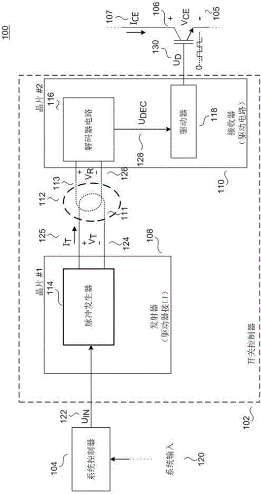
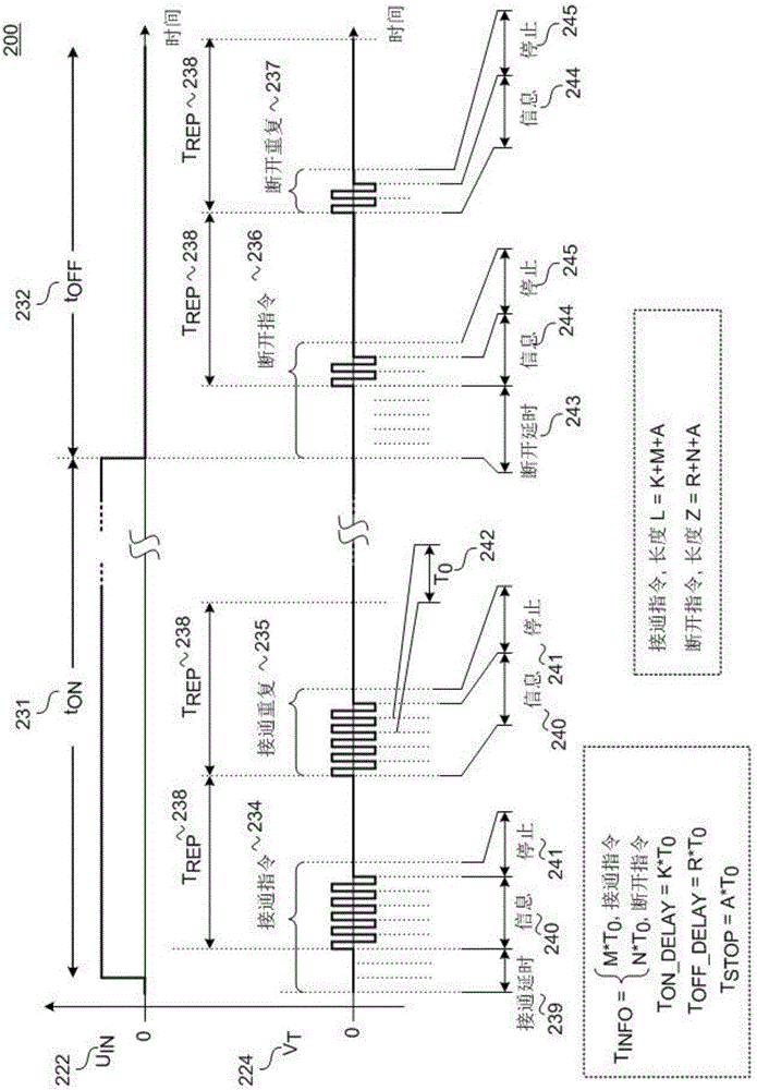
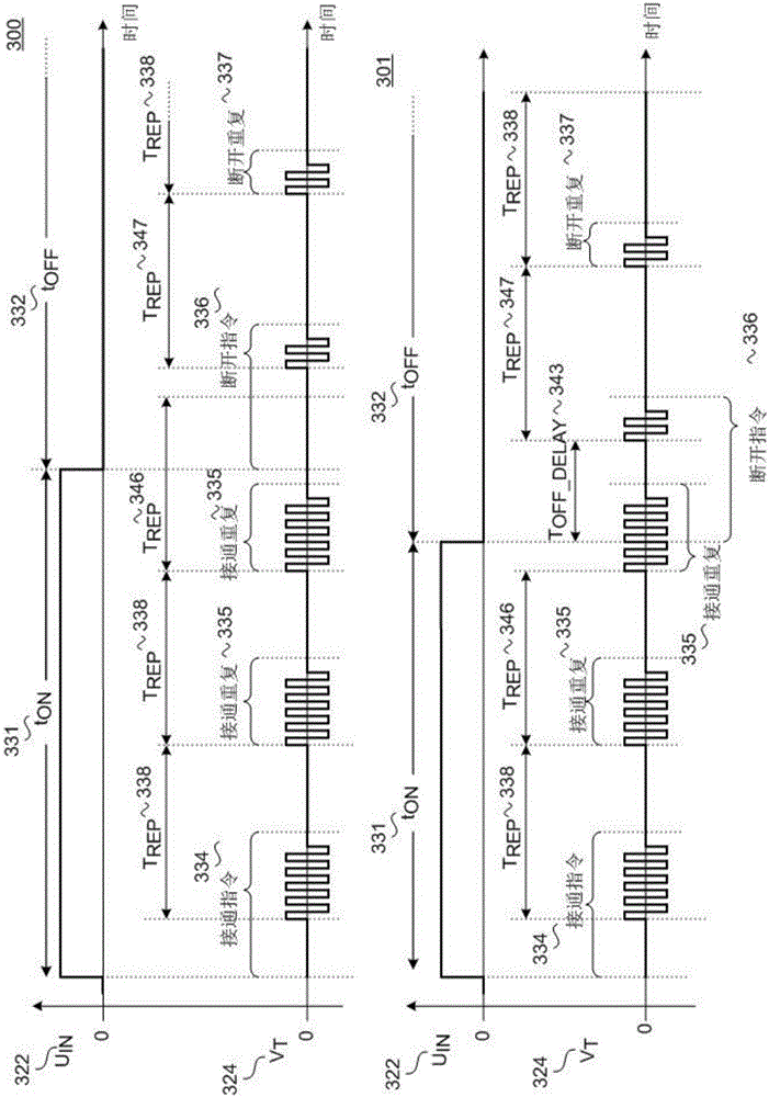
A signal transmission system for communicating across galvanic isolation. The signal transmission system includes first circuitry referenced 108 to a first potential, the first circuitry comprising signal transmission circuitry, second circuitry 110 referenced to a second potential and galvanically isolated from the first circuitry, the second circuitry comprising signal reception circuitry, and a magnetic coupling 112 between the first circuitry to the second circuitry across the galvanic isolation, the magnetic coupling comprising a transmitter-side inductor and a receiver-side inductor. The signal transmission circuitry can include a source coupled to output, to the transmitter-side inductor of the magnetic coupling, a first state representation that represents a first logic state with multiple transitions, the first state representation including at least a first upward transition, a first downward transition, a second upward transition, and a second downward transition.

Description

technical field [0001] The present disclosure generally relates to communication between a receiver and a transmitter across galvanic isolation using an inductive coupling, such as in the case of a power converter in which the primary side is galvanically isolated from the secondary side. Background technique [0002] Electronic equipment in many cases includes a communication system that sends information between a transmitter and receiver that are galvanically isolated and thus referenced to different ground potentials. Examples include power converters, medical equipment, marine equipment, and similar equipment. [0003] One such communication system utilizes magnetically coupled wires to send information between a transmitter and receiver. Inductive couplings are also known, in which a varying current flowing through a transmitting conductor induces a varying voltage across a receiving conductor. Coupling between conductors can be enhanced in a number of ways. For exa...

Claims


Application Information

Patent Timeline
IPC IPC(8): H02M1/08H02M3/155
CPCH02M1/08H02M3/155H04L25/0266H03K17/691H03K5/05H02M3/07H03H7/06H03K17/567
Inventor 马提亚·彼得简·塔尔海姆
Owner POWER INTEGRATIONS SWITZERLAND
Learn More