A wideband gps antenna
A GPS antenna and wideband technology, applied in the field of new wideband GPS antennas, can solve problems such as inability to apply satellite-borne GPS antennas, fail to meet space environment requirements, and difficult to meet application requirements, so as to achieve mass application, convenient application, and design easy effect
Active Publication Date: 2013-10-23
XIAN INSTITUE OF SPACE RADIO TECH
View PDF0 Cites 0 Cited by
- Summary
- Abstract
- Description
- Claims
- Application Information
AI Technical Summary
Problems solved by technology
Existing public or known broadband/dual-band GPS antenna structures are difficult to meet application requirements
Commonly used GPS antennas mostly use microstrip antennas and dielectric-loaded helical antennas (see literature: Overv i ew of GPS Antennas, Author: Ely Levine, Afeka Te
Method used
View moreImage
Smart ImageViewing Examples

Examples
Embodiment Construction
Login to view more PUM
 Abstract
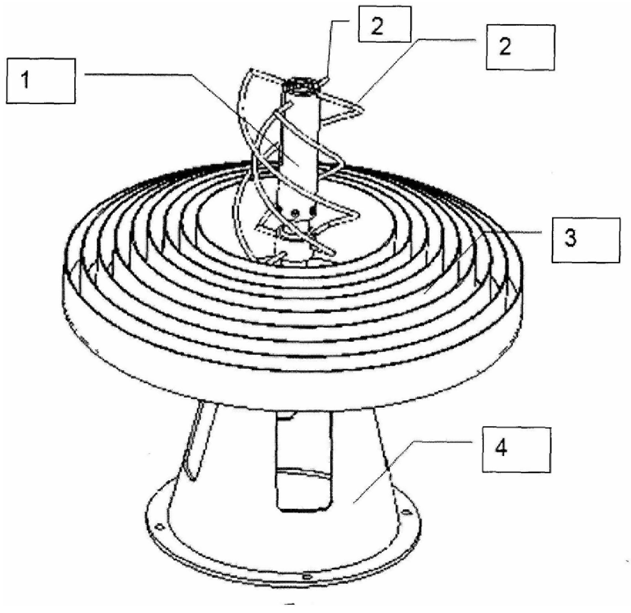
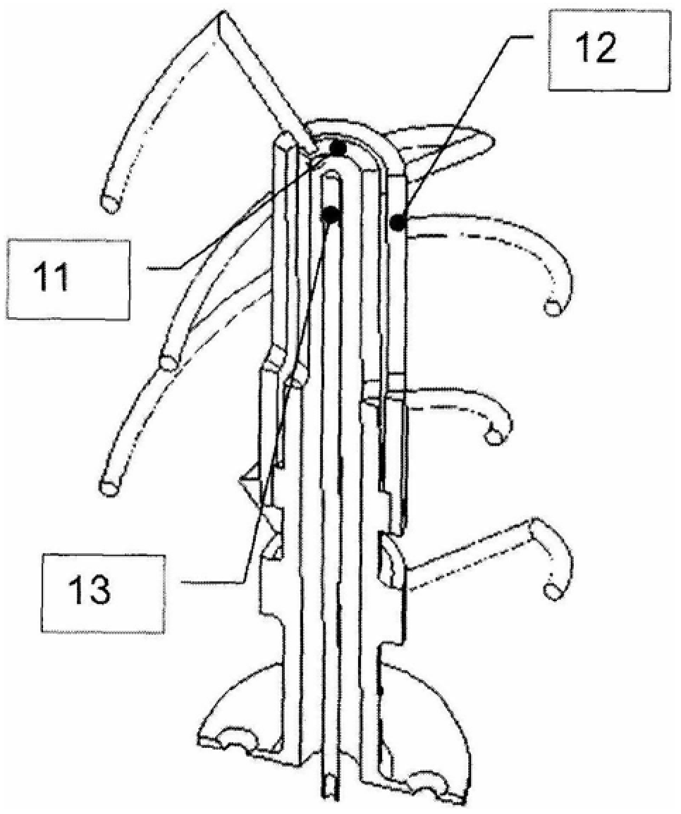
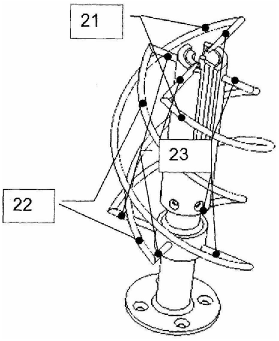
A broadband GPS antenna, the choke ring is composed of a multi-layer concentric metal ring wall with a central cavity and a common metal floor under the multi-layer concentric metal ring wall, the output SMA connector is installed under the metal floor and connected to the support Connection; two pairs of double-armed helical units and a broadband impedance transformer are installed in the central cavity of the choke ring; the inner tube of the coaxial sleeve and the outer tube of the coaxial sleeve have symmetrical slots, the symmetrical slots are in the same direction and the slotted lines are coupled ; One symmetrical arm of the double-arm spiral unit is directly welded to the upper and lower ends of the coaxial sleeve outer tube; the upper end of the other symmetrical arm bridges the upper end of the coaxial sleeve inner tube and the coaxial sleeve outer tube by welding, and its lower end Welded at the lower end of the outer tube of the coaxial sleeve; the lower end of the inner tube of the coaxial sleeve and the outer tube of the coaxial sleeve are sealed and connected by brazing; the upper end of one side of the symmetrical groove of the inner tube of the coaxial sleeve is coaxial with the center through a short circuit arc The inner conductor is connected, and the lower end of the inner conductor is connected to the output SMA connector through the coaxial medium support terminal.
Description
A wideband GPS antenna technical field The invention relates to a new broadband GPS antenna with a stable phase center, which belongs to the technical field of antennas, in particular to a design of a broadband impedance converter according to application requirements, and innovatively improves the broadband impedance converter, spiral structure, choke The combined structure of rings, as well as the ideas and methods for similar designs. Background technique With the continuous deepening and wide application of satellite navigation technology, not only ordinary ground vehicles or ships need to navigate, but also various space application platforms (such as spacecraft, satellites, space probes, aircraft, etc.) are increasingly dependent on satellite navigation. Information and positioning data, and the requirements for positioning accuracy are getting higher and higher. This requires not only to equip various platforms with adaptive GPS receiving terminals, but also to rec...
Claims
Login to view more Application Information
Patent Timeline
 IPC IPC(8): H01Q1/00H01Q1/36H01Q1/12
Inventor 张明涛冯尚森
Owner XIAN INSTITUE OF SPACE RADIO TECH
- R&D Engineer
- R&D Manager
- IP Professional
Why Eureka
- Industry Leading Data Capabilities
- Powerful AI technology
- Patent DNA Extraction
Try Eureka
Browse by: Latest US Patents, China's latest patents, Technical Efficacy Thesaurus, Application Domain, Technology Topic.
© 2024 PatSnap. All rights reserved.Legal|Privacy policy|Modern Slavery Act Transparency Statement|Sitemap