Special clamp for welding thin-walled conical body

A special fixture and cone technology, applied in welding equipment, auxiliary welding equipment, welding/cutting auxiliary equipment, etc., can solve the problems of difficult welding, poor welding quality, difficult positioning of elasticity and shape, etc., and achieve reliable clamping effect , flexible and convenient operation, and the effect of ensuring welding quality

Inactive Publication Date: 2017-01-25
HARBIN JIANCHENG GRP
View PDF5 Cites 1 Cited by
  • Summary
  • Abstract
  • Description
  • Claims
  • Application Information

AI Technical Summary

Problems solved by technology

[0003] In order to solve the problem that the gaps of the thin-walled conical body due to its own elasticity are eliminated by welding, it is difficult to locate because of its own elasticity and shape, resulting in difficult welding and poor welding quality, and further proposes a thin-walled conical body welding Special fixture

Method used


Image

  • Special clamp for welding thin-walled conical body
  • Special clamp for welding thin-walled conical body
  • Special clamp for welding thin-walled conical body

Examples


specific Embodiment approach 1

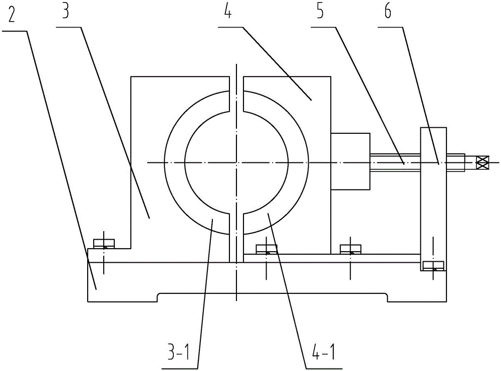
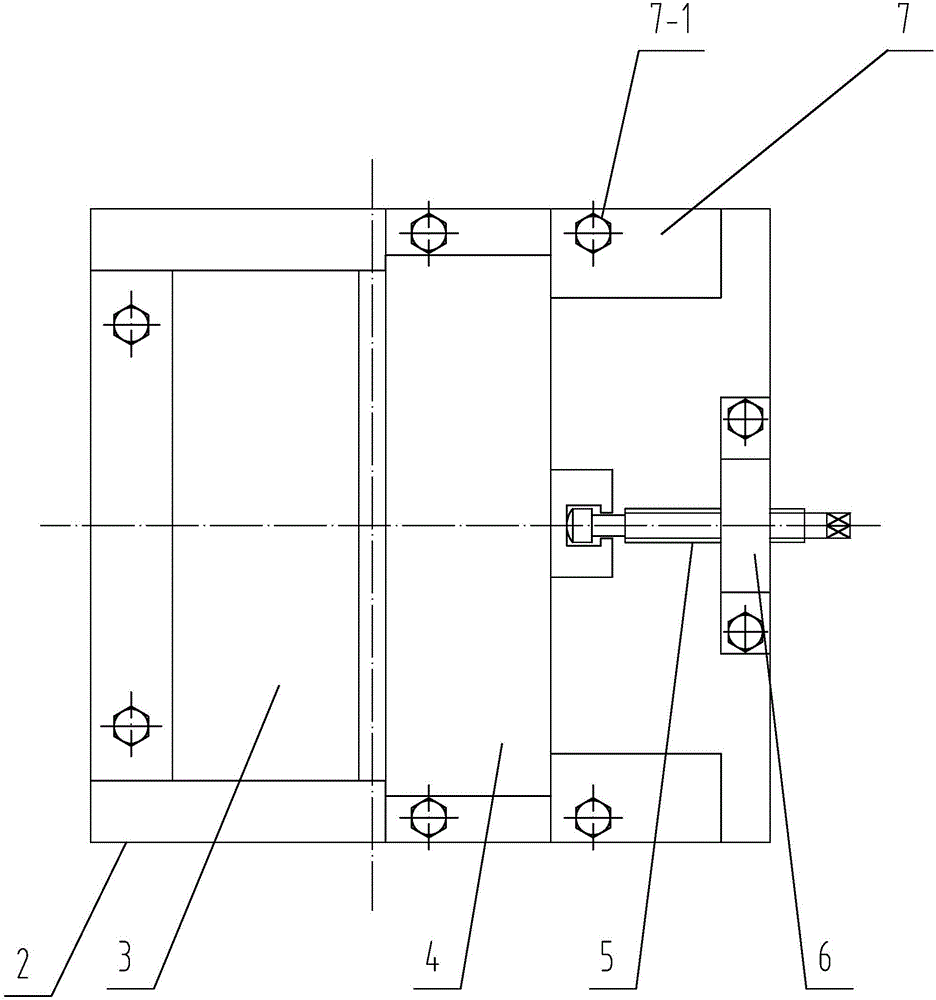
[0024] Specific implementation mode one: combine Figure 1 to Figure 15 Describe this embodiment, this embodiment comprises a base 2, a fixed block 3, a movable block 4, a screw 5, a support 6 and two pressure plates 7, the base 2 is horizontally arranged, and the two ends of the top surface of the base 2 are respectively processed There is a boss 2-2, and the fixed block 3 is fixedly connected between the two bosses 2-2. One end surface of the fixed block 3 is processed with a first tapered groove 3-1, and the movable block 4 is set Between the two bosses 2-2 and sliding fit with the base 2, the end surface of the movable block 4 facing the fixed block 3 is processed with a second tapered groove 4-1, and the first tapered groove 3-1 Set opposite to the second tapered groove 4-1, the support 6 is set on the base 2, the screw 5 passes through the support 6 to connect with the movable block 4, and the pressure plate 7 corresponds to the boss 2-2 one by one It is provided that b...

specific Embodiment approach 2

[0030] Specific implementation mode two: combination figure 1 , figure 2 , Figure 4 to Figure 11 This embodiment is described. In this embodiment, the end of the fixed block 3 far away from the movable block 4 is processed with a plurality of first connection holes 3-3, and the base 2 is processed with holes corresponding to the first connection holes 3-3. A plurality of second connection holes 2-5, the fixed block 3 is fixedly connected with the plurality of second connection holes 2-5 of the base 2 through the plurality of first connection holes 3-3. The structures and connections not mentioned in this embodiment are the same as those in the first embodiment.

specific Embodiment approach 3

[0031] Specific implementation mode three: combination figure 2 , Figure 9 , Figure 10 and Figure 11 Describe the present embodiment, the two ends of the movable block 4 in the present embodiment are each processed with a slot 4-2, the slot 4-2 is set in one-to-one correspondence with the pressing plate 7, and one end of each pressing plate 7 is inserted into it. Corresponding slot 4-2. The structures and connections not mentioned in this embodiment are the same as those in the first or second embodiment.


PUM


Abstract

The invention discloses a special clamp for welding a thin-walled conical body, relates to a special welding clamp, and aims at solving the problems that the welding difficulty is larger and the welding quality is poor caused by difficult positioning due to the self elasticity and shape of the thin-walled conical body when a gap, generated by the self elasticity, of the thin-walled conical body is eliminated through a welding manner. Bosses are processed on the two ends of the top surface of a base respectively; a fixed block is fixedly connected between the two bosses; a first conical groove is processed in one end surface of the fixed block; a movable block is arranged between the two bosses and is ;in sliding fit with the base; a second conical groove is formed in one end surface, facing the fixed block, of the movable block; the first conical groove is opposite to the second conical groove; a supporting seat is arranged on the base; a screw rod penetrates through the supporting seat and is connected with the movable block; pressure plates are arranged corresponding to the bosses one by one; the two ends of the movable block are compressed on the base through the corresponding pressure plates; and each pressure plate is detachably connected to the corresponding boss. The special clamp for welding the thin-walled conical body is used for positioning the thin-walled conical body.

Description

technical field [0001] The invention specifically relates to a special fixture for welding thin-walled cones. Background technique [0002] In mechanical processing, especially in the processing of military equipment, it often involves processing a thin-walled cone, which is a tapered cylinder. This part is made according to the size requirements of the relevant drawings. The steel plate with a thickness of one to three millimeters is welded after pressing, and the material of the thin-walled cone is Q235. After the thin-walled cone is pressed, due to its own elasticity, the outer wall of the thin-walled cone exists along its axial direction. The gap, this gap makes the thin-walled cone unable to form a closed cylindrical structure, because the shape of the thin-walled cone itself makes it difficult to carry out the butt joint work of this gap, and at the same time, the peripheral edge of the small mouth end of the thin-walled cone is in contact with the large mouth during t...

Claims


Application Information

Patent Timeline
Patent Type & Authority Applications(China)
IPC IPC(8): B23K37/04
CPCB23K37/0443
Inventor 曾庆富左莹璐聂晶
Owner HARBIN JIANCHENG GRP
Why Eureka
Try Eureka