
Pipe fitting clamping device

A technology of pipe clamps and clamping blocks, which is applied in the direction of positioning devices, clamping, metal processing machinery parts, etc., can solve the problems of poor shock absorption effect and need to improve the clamping force, and achieve the effect of improving the shock absorption effect

Inactive Publication Date: 2017-01-25
周末
View PDF6 Cites 17 Cited by
  • Summary
  • Abstract
  • Description
  • Claims
  • Application Information

AI Technical Summary

Problems solved by technology

[0002] At present, round pipe fittings need to be clamped during processing, so as to prevent pipe fittings from shifting. Generally, pipe fitting clamping devices are used, but the clamping force of current pipe fitting clamping devices needs to be Improvement, on the other hand, the shock absorption effect is poor, and needs to be further improved

Method used


Image

  • Pipe fitting clamping device

Examples


Embodiment Construction

[0012] In order to make the object, technical solution and advantages of the present invention clearer, the present invention will be further described in detail below in conjunction with the accompanying drawings and embodiments. It should be understood that the specific embodiments described here are only used to explain the present invention, not to limit the present invention.

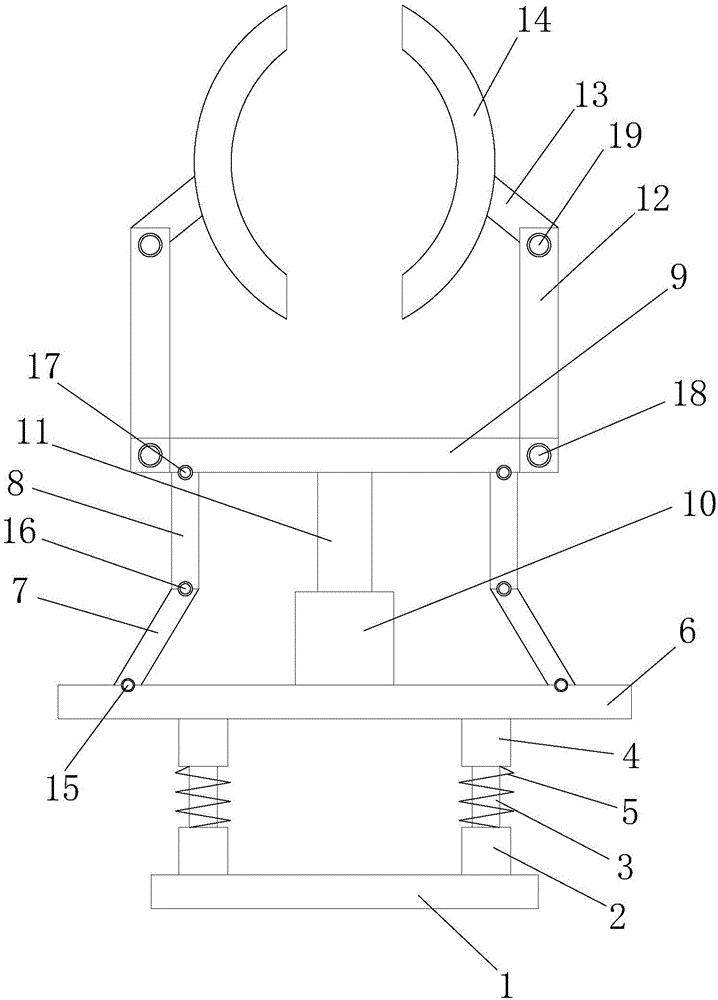
[0013] Such as figure 1 As shown, the clamping device for pipe fittings includes a base 1 on which a lower support sleeve 2 is vertically installed, and a telescopic rod 3 is installed on the lower support sleeve 2. An upper support sleeve 4 is installed above the rod 3, and a shock absorbing spring 5 is arranged outside the telescopic rod 3, and a support plate 6 is installed on the upper support sleeve 4, and a support plate 6 is installed on the support plate 6. Connecting rods A7 are respectively installed on both sides, and connecting rods B8 are movably installed on the connecting rods A7. ...


PUM


Abstract

The invention discloses a pipe fitting clamping device which comprises a base. Lower supporting sleeves are vertically mounted on the base; telescopic rods are mounted on the lower supporting sleeves; upper supporting sleeves are mounted above the telescopic rods, and damping springs are arranged outside the telescopic rods; a supporting plate is mounted on the upper supporting sleeves; connecting rods A are respectively mounted at both sides of the supporting plate; connecting rods B are movably mounted on the connecting rods A ; the top ends of the connecting rods B are mounted below a pushing rod, and a driver is mounted at the middle position at the upper end of the supporting plate; a drive rod is mounted on the driver; the top end of the drive rod drives the pushing rod to move, and movable rods are movably mounted at both sides of the pushing rod; inclined rods are movably mounted at the upper ends of the movable rods; clamping blocks are mounted at one ends of the inclined rods. In the using process of the pipe fitting clamping device, a pipe fitting is arranged between the clamping blocks, and driving is carried out by the driver to drive the clamping blocks to carry out a clamping operation on the pipe fitting; by arranging the damping springs, a damping effect of the integral device can be improved.

Description

technical field [0001] The invention relates to the field of clamping technology, in particular to a pipe clamping device. Background technique [0002] At present, round pipe fittings need to be clamped during processing, so as to prevent pipe fittings from shifting. Generally, pipe fitting clamping devices are used, but the clamping force of current pipe fitting clamping devices needs to be Improvement, on the other hand, the shock absorption effect is poor and needs to be further improved. Contents of the invention [0003] In order to overcome the deficiencies in the prior art, the present invention provides a clamping device for pipe fittings. [0004] The present invention is realized through the following technical solutions: [0005] A clamping device for pipe fittings, comprising a base, a lower support sleeve is vertically installed on the base, a telescopic rod is installed on the lower support sleeve, and an upper support sleeve is installed above the telesco...

Claims


Application Information

Patent Timeline
Patent Type & Authority Applications(China)
IPC IPC(8): B23Q3/08
CPCB23Q3/08B23Q3/082
Inventor 周末
Owner 周末
Learn More