Pipeline potential monitoring device and method for synchronously monitoring potentials in different areas of pipeline

A potential monitoring and pipeline technology, which is applied in the field of corrosion monitoring and detection, can solve the problems of inconvenient installation and use, inability to collect pipeline potential data intensively, and difficulty in realizing potential measurement, etc., and achieve the effect of convenient installation and use

Active Publication Date: 2017-01-25
青岛钢研纳克检测防护技术有限公司
3 Cites 3 Cited by

AI-Extracted Technical Summary

Problems solved by technology

In seawater pipelines, conventional potential measurement methods: hand-held underwater potentiometer or portable reference electrode, it is difficult to measure potential
However, using point-like reference electrodes to monitor ...

Method used

Between described lower mounting flange 16 and the PE protection pipe 10 of linear reference electrode 4, be provided with sealing pressure ring 18 and the first sealing ring 20 successively from top to bottom; Described sealing pressure ring 18 and wire A second ...

Abstract

The invention belongs to the field of corrosion monitoring and particularly relates to a device for monitoring the potentials in different areas in a seawater pipeline and synchronously monitoring the potentials in different areas of a pipeline. The device comprises a multi-channel potential collector (1), a linear reference electrode (4) and mounting flanges (3), wherein the linear reference electrode (4) is mounted in a to-be-monitored pipeline (23) through the mounting flanges (3) at the two ends; the linear reference electrode (4) is connected with the multi-channel potential collector (1) through a multi-core shield cable (2); the reference ground end of the multi-channel potential collector (1) is connected with the to-be-monitored pipeline (23) through a reference ground cable (5); and the linear reference electrode (4) is of a linear array structure and comprises multiple reference electrode units in uniform distribution. The device provided by the invention has the advantages of convenience in mounting, easiness in operation and convenience in use and can quickly measure and record the cathode protection potentials in different areas inside the pipeline.

Technology Topic

Image

  • Pipeline potential monitoring device and method for synchronously monitoring potentials in different areas of pipeline
  • Pipeline potential monitoring device and method for synchronously monitoring potentials in different areas of pipeline
  • Pipeline potential monitoring device and method for synchronously monitoring potentials in different areas of pipeline

Examples

  • Experimental program(1)

Example Embodiment

[0043] The present invention will be further described below in conjunction with embodiments.
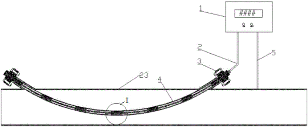
[0044] Such as figure 1 As shown, a pipeline potential monitoring device of the present invention includes a multi-channel potential collector 1, a linear reference electrode 4 and a mounting flange 3.
[0045] Wherein, the linear reference electrode 4 is installed inside the pipeline 23 to be tested through mounting flanges 3 provided at both ends; the linear reference electrode 4 is connected to the multi-channel potential collector 1 through a multi-core shielded cable 2; The reference ground terminal of the channel potential collector 1 is connected to the pipeline 23 to be measured through a reference ground cable 5.
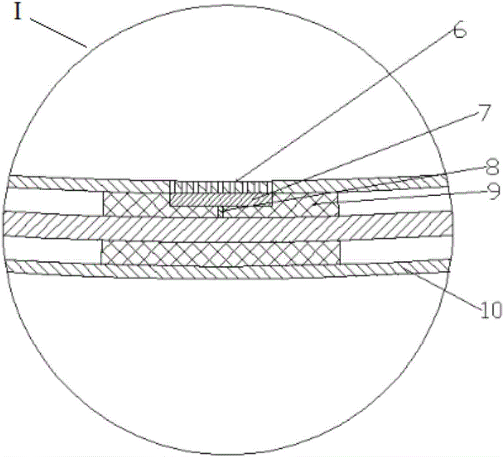
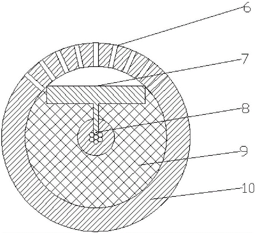
[0046] The linear reference electrode 4 is a linear array structure and includes a plurality of evenly distributed reference electrode units. The number and spacing of the reference electrode units are designed according to the area of ​​the pipeline 23 to be tested that needs to be monitored. For example, a 5-meter pipeline requires 4 monitoring points and no special monitoring area, so the number of reference electrodes is 4, and the separation distance is 1 meter.
[0047] Such as figure 2 with image 3 As shown, the reference electrode unit includes a silver/silver chloride reference electrode 7. The silver/silver chloride reference electrode 7 is connected to a cable core 8 in the multi-core shielded cable 2 in one-to-one correspondence, that is, different silver/chlorine The silver reference electrode 7 is connected to different cable cores 8; the outer layer of the silver/silver chloride reference electrode 7 and the multi-core shielded cable 2 is wrapped with a PVC cylinder 9 formed by injection molding; the outer layer of the PVC cylinder 9 is provided with The PE protective tube 10 is provided with a plurality of electrode holes 6 on the PE protective tube 10, and the electrode holes 6 are located above the silver/silver chloride reference electrode 7.
[0048] Such as Figure 4 As shown, both ends of the PE protective pipe 10 are sealed with sealant 21.
[0049] Such as Figure 4 As shown, the mounting flange 3 includes an upper mounting flange 15 and a lower mounting flange 16;
[0050] The lower mounting flange 16 is welded to the pipeline 23 to be tested through the flange base 22; the included angle between the flange base 22 and the pipeline 23 to be tested is 30-60 degrees, preferably 45 degrees, which is convenient for linearity The reference electrode 4 passes through the lower mounting flange 16.
[0051] A sealing pressing ring 18 and a first sealing ring 20 are sequentially arranged between the lower mounting flange 16 and the PE protective tube 10 of the linear reference electrode 4 from top to bottom; the sealing pressing ring 18 and the linear reference A second sealing ring 19 is arranged between the PE protective pipe 10 of the electrode 4, and the second sealing ring 19 and the first sealing ring 20 can ensure the tightness of the linear reference electrode 4 installed on the pipeline 23 to be tested.
[0052] The upper mounting flange 15 is fixedly connected to the lower mounting flange 16 by connecting bolts 17. A limit nut 14 is provided between the upper mounting flange 15 and the PE protective tube 10 of the linear reference electrode 4, and the limit nut 14 is matched with the thread on the outer surface of the PE protective tube 10 to install the linear reference electrode 4 with the upper Flange 15 is fixed. A waterproof cap 12 is installed on the upper mounting flange 15 through bolts 13, and a cable sealing head 11 is installed on the waterproof cap 12.
[0053] The multi-channel potential collector 1 can simultaneously collect, display and store the potentials of all reference electrode units relative to the pipeline 23 to be tested. The multi-channel potential collector 1 is provided with an RS485 interface and a GPRS transmitter, and can transmit data to a computer via a cable or GPRS signal.
[0054] The method of the present invention for simultaneously monitoring the potentials of different areas of the pipeline includes:
[0055] A hole is opened at both ends of the pipeline 23 to be measured that needs to monitor the potential, and the linear reference electrode 4 of the pipeline potential monitoring device is installed inside the pipeline 23 to be measured through the mounting flanges 3 provided at both ends;
[0056] The medium is introduced into the pipeline 23 to be tested, and the multi-channel potential collector 1 is turned on to start monitoring and recording the potentials of different areas on the inner wall of the pipeline 23 to be tested.
[0057] The working process of the present invention is as follows:
[0058] Open a hole at both ends of the pipeline 23 to be measured that needs to monitor the potential, and weld the flange base 22 of the mounting flange 16 respectively, and pass the linear reference electrode 4 out of the mounting flange 16 at both ends, And fixed by the upper mounting flange 15.
[0059] Connect the linear reference electrode 4 to the corresponding multiple reference terminals of the multi-channel potential collector 1 through the multi-core shielded cable 2, and then connect the reference ground terminal of the multi-channel data collector 1 through the reference ground cable 5 Connect with the pipeline 23 to be tested.
[0060] Pass the medium into the pipeline 23 to be tested, and turn on the multi-channel potential collector 1 to start monitoring and recording the potential of different areas on the inner wall of the pipeline. In actual operation, the position and separation distance of the silver/silver chloride reference electrode 7 in the linear reference electrode 4 can be set according to the pipeline position to be monitored.
[0061] Through RS485 interface and GPRS signal, the monitoring data can be transmitted to the computer for real-time monitoring, or the data can be further analyzed.

PUM

no PUM

Description & Claims & Application Information

We can also present the details of the Description, Claims and Application information to help users get a comprehensive understanding of the technical details of the patent, such as background art, summary of invention, brief description of drawings, description of embodiments, and other original content. On the other hand, users can also determine the specific scope of protection of the technology through the list of claims; as well as understand the changes in the life cycle of the technology with the presentation of the patent timeline. Login to view more.

Similar technology patents

Automatic Wheel Chock System

InactiveUS20140188334A1Easy to install and useBraking element arrangementsPortable braking systemWheel chockActuator
Owner:FOSTER CHRISTOPHER R

Classification and recommendation of technical efficacy words

Why Eureka
Try Eureka