A Smart Integrated Monitor for Pressure Flow of Air Source System

A system pressure and comprehensive monitoring technology, applied in the direction of fluid pressure control, control/regulation system, electric fluid pressure control, etc., can solve the problem of limiting the flexibility and reliability of gas source system detection work, detection data, accuracy and detection Problems such as method differences and low efficiency of gas source system detection work can be achieved to improve operating efficiency and detection accuracy, improve flexibility and reliability, and use flexibility and convenience

Inactive Publication Date: 2017-01-25
成都润博科技有限公司
View PDF6 Cites 2 Cited by
  • Summary
  • Abstract
  • Description
  • Claims
  • Application Information

AI Technical Summary

Problems solved by technology

[0002] The main function of the air source system is to provide an air source with high-precision pressure and flow parameters. The performance and accuracy of the air source system directly affect the coordination and correctness of the work of the control system, which plays a vital role in many equipment In order to improve the reliability and stability of the air source system, a large number of air source system detection devices based on mechanical automation systems or based on operator operations have been developed, although these devices can meet the requirements of use to a certain extent. However, on the one hand, the equipment results of each device are relatively complicated, and the degree of operation automation is not high, and there are great differences in the detection data, accuracy and detection methods of each device, resulting in relatively low working efficiency of Dangqi gas source system detection work. low, and the lack of commonality among the inspection data of different equipment greatly limits the flexibility and reliability of the gas source system detection work. Therefore, in response to this problem, it is urgent to develop a unified gas source device detection equipment to Meet the needs of actual use

Method used


Image

  • A Smart Integrated Monitor for Pressure Flow of Air Source System
  • A Smart Integrated Monitor for Pressure Flow of Air Source System

Examples


Embodiment Construction

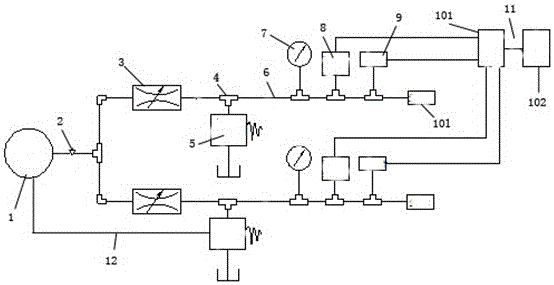
[0013] Such as figure 1 with 2 A gas source system pressure and flow intelligent comprehensive monitor is shown, including a simulated gas source 1, a control valve 2, a pressure reducer 3, a regulating valve 4, an overflow valve 5, a diversion tube 6, a pressure detection device 7, a pressure variable transmitter 8, flow sensor 9, simulated load 10, and control system 11. The simulated air source 1 is connected to the test pipeline through the control valve 2. There are at least two test pipelines. Each test pipeline is connected in parallel with each other, and each test pipeline The pipelines are all connected to at least one simulated load 10, and the test pipelines include a guide tube 6, a pressure reducer 3, a control valve 2, a relief valve 4, a pressure detection device 7, a pressure transmitter 8 and a flow sensor 9, wherein The pressure reducer 3 communicates with the control valve 2, the overflow valve 5 and the pressure detection device 7 respectively through the...


PUM


Abstract

This invention discloses a smart integrated monitor for pressure flow of air source system, comprising simulated air source, a control valve, a pressure reducer, a regulating valve, a relief valve, a draft tube, a pressure detection device, a pressure transmitter, a flow sensor, simulated load and a control system. The simulation air source is connected with the test pipeline the through the control valve. There are at least two test pipelines, which are connected parallel to each other. Each test pipeline is connected with at least one simulation load. The test pipeline consists of a draft tube, a pressure reducer, a regulating valve, a relief valve, a pressure detection device, a pressure transmitter and a flow sensor. The control system comprises a data collecting device and a control computer platform. The smart integrated monitor for pressure flow of air source system can, on one hand, effectively improve the operation efficiency and detection accuracy of the gas source detection device, and on the other hand can effectively improve the integration of different detection data, and improve the flexibility and reliability of the gas source detection system.

Description

technical field [0001] The invention relates to an intelligent comprehensive monitor for pressure and flow of an air source system, which belongs to the technical field of textile production. Background technique [0002] The main function of the air source system is to provide an air source with high-precision pressure and flow parameters. The performance and accuracy of the air source system directly affect the coordination and correctness of the work of the control system, which plays a vital role in many equipment In order to improve the reliability and stability of the air source system, a large number of air source system detection devices based on mechanical automation systems or based on operator operations have been developed, although these devices can meet the requirements of use to a certain extent. However, on the one hand, the equipment results of each device are relatively complicated, and the degree of operation automation is not high, and there are great dif...

Claims


Application Information

Patent Timeline
Patent Type & Authority Applications(China)
IPC IPC(8): G01D21/02G05D16/20
CPCG01D21/02G05D16/2026
Inventor 周明军黄东张小兵曾尚姚中伟
Owner 成都润博科技有限公司
Why Eureka
Try Eureka