
Power equipment inspection device based on RFID (Radio Frequency Identification Device) electronic tag

A technology of RFID tags and power equipment, applied in the direction of collaborative operation devices, inspection time patrols, instruments, etc., can solve the problem that information cannot be timely feedback and statistics, inspection quality and availability rate cannot be guaranteed, and equipment hidden dangers cannot be timely. Discovery and other problems, to achieve the effect of reducing communication costs, reducing human error, and easy installation

Inactive Publication Date: 2017-01-25
HAIXI POWER SUPPLY COMPANY OF STATE GRID QINGHAI ELECTRIC POWER +2
View PDF13 Cites 11 Cited by
  • Summary
  • Abstract
  • Description
  • Claims
  • Application Information

AI Technical Summary

Problems solved by technology

Due to the constraints of various factors such as climatic conditions, environmental factors, personnel quality and sense of responsibility, the inspection quality and arrival rate cannot be guaranteed
Colleagues, the information reflecting the operating status and equipment defects cannot be timely fed back and counted, resulting in defects that cannot be processed in time, hidden dangers of equipment cannot be discovered in time, and equipment failures
In addition, it is difficult to effectively supervise the inspectors by using traditional inspection management methods, and equipment accidents caused by inadequate inspections are not uncommon.

Method used


Image

  • Power equipment inspection device based on RFID (Radio Frequency Identification Device) electronic tag
  • Power equipment inspection device based on RFID (Radio Frequency Identification Device) electronic tag
  • Power equipment inspection device based on RFID (Radio Frequency Identification Device) electronic tag

Examples


Embodiment Construction

[0026] In order to clearly illustrate the technical features of this solution, the present invention will be described in detail below through specific implementation modes and in conjunction with the accompanying drawings. The following disclosure provides many different embodiments or examples for implementing different structures of the present invention. To simplify the disclosure of the present invention, components and arrangements of specific examples are described below. Furthermore, the present invention may repeat reference numerals and / or letters in different instances. This repetition is for the purpose of simplicity and clarity and does not in itself indicate a relationship between the various embodiments and / or arrangements discussed. It should be noted that components illustrated in the figures are not necessarily drawn to scale. Descriptions of well-known components and processing techniques and processes are omitted herein to avoid unnecessarily limiting the...


PUM


Abstract

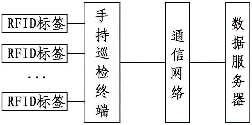
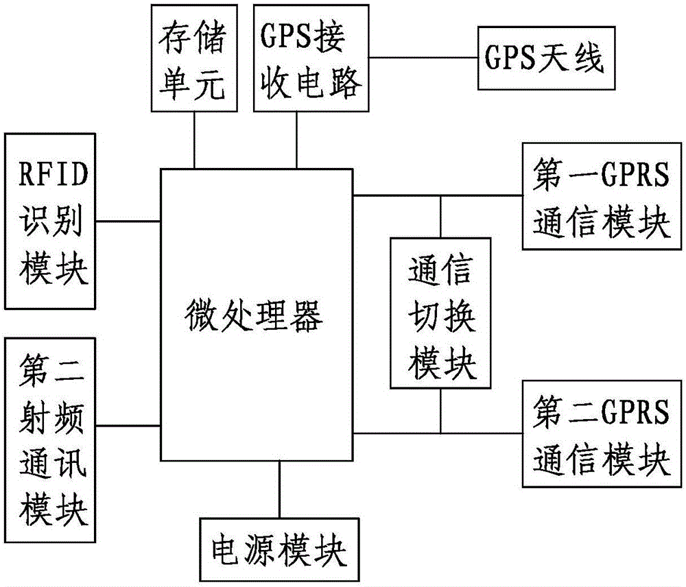
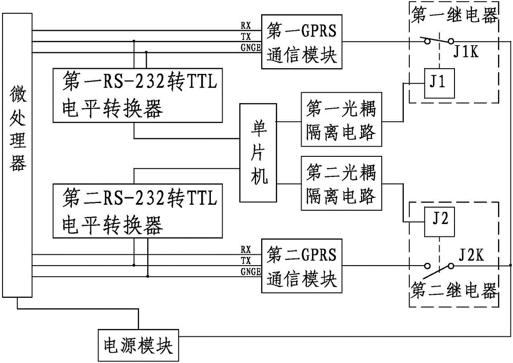
The invention discloses a power equipment inspection device based on an RFID (Radio Frequency Identification Device) electronic tag. The power equipment inspection device comprises multiple RFID tags, a handheld inspection terminal, a communication network and a data server located in a monitoring center, wherein the multiple RFID tags are respectively adhered to to-be-inspected power equipment and are used for storing communication information of power equipment in a character string way, and the communication information comprises an ID (Identity), the channel type and the channel parameters of the to-be-inspected power equipment; the handheld inspection terminal is used for reading a character string of the communication information, which is stored in the tags, of the to-be-inspected power equipment, and sending the obtained ID, the obtained channel type and the obtained channel parameters of the to-be-inspected power equipment to the data server through the communication network; the data server is used for receiving and storing inspection data of the power equipment so as to enable each inquire terminal to inquire. According to the power equipment inspection device disclosed by the invention, the inspection data can be transmitted to a management center in time, so that technical staff in the management center can know equipment situations in time, and a technical support is provided for inspection staff.

Description

technical field [0001] The invention relates to a power equipment patrol inspection device, in particular to a power equipment patrol inspection device based on an RFID electronic tag, and belongs to the technical field of power equipment patrol inspection. Background technique [0002] With the continuous development of society, the demand for power resources is increasing day by day. In order to ensure the safe, reliable and economical operation of power equipment and reduce the occurrence of accidents, it is an effective method to regularly inspect the equipment. At present, my country's power equipment inspections mainly rely on inspection personnel to conduct manual inspections on a regular basis. Due to the constraints of various factors such as climate conditions, environmental factors, personnel quality and sense of responsibility, the quality and availability of inspections cannot be guaranteed. At the same time, the information reflecting the operating status and...

Claims


Application Information

Patent Timeline
Patent Type & Authority Applications(China)
IPC IPC(8): G07C1/20G06K17/00
CPCG07C1/20G06K17/0022
Inventor 赵秀梅陈云李龙董耀张银亲莫超赵浩翔杨怀建严冬梅张功平李向宇沈恒山郭海庆王成张兴田冰魏延迪
Owner HAIXI POWER SUPPLY COMPANY OF STATE GRID QINGHAI ELECTRIC POWER
Learn More