Knee joint load-bearing power assisting exoskeleton device and working method thereof

A knee joint and exoskeleton technology, applied in the manufacture of tools, appliances to help people walk, manipulators, etc., can solve the problems of large structural errors, complex structures, and large volumes, and achieve small structural errors, small volume, and easy operation. simple effect

Inactive Publication Date: 2017-02-01
FUZHOU UNIV
View PDF8 Cites 8 Cited by
  • Summary
  • Abstract
  • Description
  • Claims
  • Application Information

AI Technical Summary

Problems solved by technology

There are relatively few exoskeleton assisting products for the lower limbs of normal people. Even though some research institutions have developed sim

Method used


Image

  • Knee joint load-bearing power assisting exoskeleton device and working method thereof
  • Knee joint load-bearing power assisting exoskeleton device and working method thereof
  • Knee joint load-bearing power assisting exoskeleton device and working method thereof

Examples


Embodiment Construction

[0023] In order to make the above-mentioned features and advantages of the present invention more obvious and easy to understand, the following specific embodiments are given and the accompanying drawings are described in detail as follows.

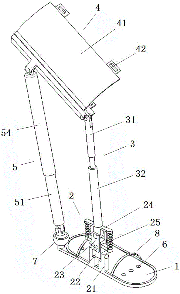
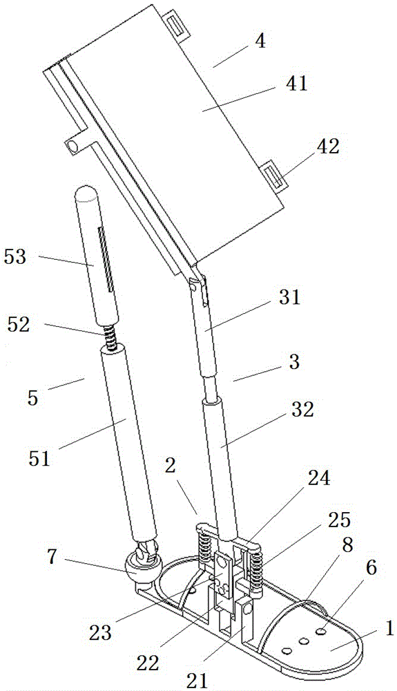
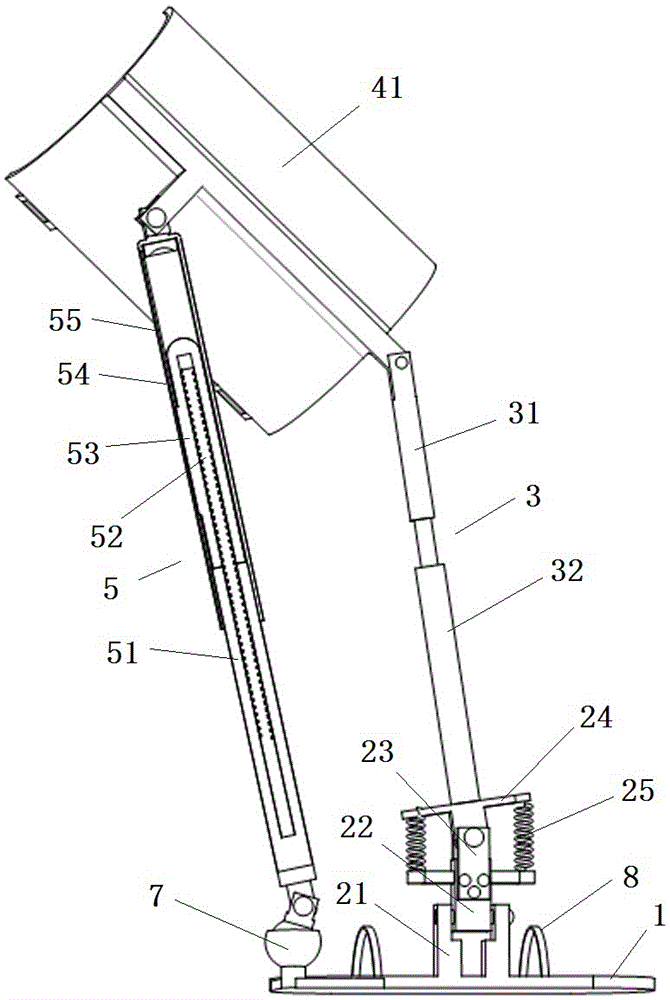
[0024] like Figures 1~4 As shown, a knee joint weight-bearing exoskeleton device includes a sole plate 1, an ankle joint 2 is provided at the outer end of the sole plate 1, and the ankle joint 2 is hinged with a calf rod 3, and the calf rod 3 is hinged with the thigh rod 4, and a servo electric cylinder assembly 5 that drives the movement of the thigh rod 4 is hinged between the rear end of the foot bottom plate 1 and the thigh rod 4, and the foot bottom plate 1 is arranged with several The pressure sensor 6 is electrically connected with the control module, and the control module is electrically connected with the servo electric cylinder assembly 5 .

[0025] In the embodiment of the present invention, the servo electric cylinder assem...


PUM


Abstract

The invention relates to a knee joint load-bearing power assisting exoskeleton device which comprises a frame foot, wherein an ankle joint is arranged at the outer side end of the frame foot and is hinged to a shank rod piece, the shank rod piece is further hinged to a thigh rod piece, a servo electric cylinder component for driving the thigh rod piece to move is hinged between the rear side end of the frame foot and the thigh rod piece, a plurality of pressure sensors are distributed on the frame foot and are electrically connected with a control module, and the control module is electrically connected with the servo electric cylinder component. The invention further relates to a working method of the knee joint load-bearing power assisting exoskeleton device. The knee joint load-bearing power assisting exoskeleton device is simple, compact and reasonable in structural design, accords with ergonomics, is small in size and structural error and low in cost and energy consumption, and accords with the ideas of energy conservation and environment protection.

Description

Technical field [0001] The invention relates to a knee joint weight-bearing power-assisted exoskeleton device and a working method thereof. Background technique [0002] Most of the current lower limb exoskeleton assistance equipment adopts a semi-anthropomorphic structural design, and these are mostly used for medical purposes, that is, to help patients recover. There are relatively few exoskeleton assist products for normal people's lower limbs. Even though some research institutions have developed similar products, the common defects of these products are: complex structure, large volume, large structural errors, high cost and high energy consumption. Contents of the invention [0003] In view of the shortcomings of the existing technology, the technical problem to be solved by the present invention is to provide a knee joint weight-bearing assist exoskeleton device and its working method, which not only have a reasonable structural design, but are also efficient and co...

Claims


Application Information

Patent Timeline
IPC IPC(8): A61H3/00A61H1/02B25J9/00
CPCA61H3/00A61H1/0237A61H1/0262A61H2201/1207A61H2201/164A61H2201/165A61H2201/1659A61H2201/5071A61H2205/102B25J9/0006
Inventor 吴乙万陈正强
Owner FUZHOU UNIV
Why Eureka
Try Eureka