Drilling tool for architectural section

A technology for drilling tooling and profiles, which is applied in the field of building profile processing, can solve the problems of a small number of building profiles, a small scope of application, and low work efficiency, so as to improve drilling efficiency and drilling quality, improve versatility, and improve work efficiency. The effect of efficiency

Inactive Publication Date: 2017-02-01
芜湖瑞德机械科技有限公司
View PDF9 Cites 7 Cited by
  • Summary
  • Abstract
  • Description
  • Claims
  • Application Information

AI Technical Summary

Problems solved by technology

[0003] The purpose of the present invention is to overcome the problems of small application range, low work efficiency, and small number of building profiles for one-time drilling in the existing building profile drilling device, and to provide

Method used


Image

  • Drilling tool for architectural section
  • Drilling tool for architectural section

Examples


Example Embodiment

[0020] Example 1:

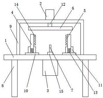
[0021] as attached figure 1 As shown in the figure, a drilling tool for building profiles includes an operation table 1, a cylinder 2, a motor 3, a bearing block 4, a bearing plate 5, a pressure plate 6, and a drill bit 7. It is characterized in that: the operation table 1 is provided with A support frame 9 and a positioning plate 10 are arranged on the bracket 8 and on the operating table 1 , the positioning plate 10 is provided with a limit block 11 , the cylinder 2 is arranged on the support frame 9 , and the cylinder 2 There is an adjustment rod 12 on the upper part, the motor 3 is arranged on the operating table 1, one end of the bearing block 4 is arranged between the limit block 11 and the limit block 11 on the positioning plate 10, the bearing block 4 and the positioning plate 10 are provided with a spring 13, the bearing block 4 is provided with a structure that can be replaced between the limiting block 11 and the limiting block 11, the bearing p...

Example Embodiment

[0027] Example 2:

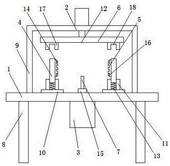
[0028] A drilling tool for building profiles, comprising an operating table 1, a cylinder 2, a motor 3, a bearing block 4, a bearing plate 5, a pressing plate 6, and a drill bit 7, characterized in that the operating table 1 is arranged on a bracket 8 On the operating table 1, a support frame 9 and a positioning plate 10 are arranged, a limit block 11 is arranged on the positioning plate 10, the cylinder 2 is arranged on the support frame 9, and the cylinder 2 is provided with a The adjusting rod 12, the motor 3 is arranged on the operating table 1, one end of the bearing block 4 is arranged between the limit block 11 and the limit block 11 on the positioning plate 10, and the bearing block 4 is connected to the positioning plate 10. A spring 13 is arranged between the plates 10, the bearing block 4 is provided with a structure that can be replaced between the limit block 11 and the limit block 11, and the bearing plate 5 is arranged on the bearing block 4 ...


PUM


Abstract

The invention discloses a drilling tool for architectural section. The drilling tool comprises an operation table, an air cylinder, a motor, bearing blocks, bearing plates, a pressing plate and a drill; the drilling tool is characterized in that the operation table is arranged on a support, a supporting frame and a positioning plate are arranged on the operation table, limiting blocks are arranged on the positioning plate, and the air cylinder is arranged on the supporting frame and provided with an adjusting rod; the motor is arranged on the operation table, one end of each bearing block is arranged between the limiting blocks on the positioning plate, and the bearing plates are arranged on the bearing blocks and provided with bearing grooves; and the pressing plate is arranged on the adjusting rod, and the drill is arranged on the motor through a connecting block. According to the drilling tool, the multiple bearing grooves are formed in the bearing plates, the firmness of the architectural section at the position between the bearing plates is improved through the bearing grooves, the stability of the building proximate matter in the drilling process is strengthened, and the drilling efficiency and the drilling quality of the building proximate matter can be further improved.

Description

technical field [0001] The invention relates to the technical field of building profile processing, in particular to a drilling tool for building profile. Background technique [0002] At present, during the processing of building profiles, screw fixing holes of different sizes need to be punched on the building profiles. Most of the existing methods are to manually punch out the holes one by one, or punch a hole first, and then punch the hole in the corresponding position. , increase the working time and labor load, for the drilling of different apertures, the drill bit must be replaced continuously, the labor intensity is high, and the drilling accuracy is low. The problem of low hole precision and poor stability, but it has the problems of small application range, low work efficiency, and a small number of building profiles for one drilling. Contents of the invention [0003] The purpose of the present invention is to overcome the problems of small application range, l...

Claims


Application Information

Patent Timeline
IPC IPC(8): B23Q3/06B23Q3/08
CPCB23Q3/061B23Q3/069B23Q3/082
Inventor 杜京奎胡已生
Owner 芜湖瑞德机械科技有限公司
Why Eureka
Try Eureka