
Underwater bionic propelling device with controllable rigidity

A propulsion device and stiffness technology, applied in the field of bionic robots, can solve the problems of limited propulsion performance improvement, change of stiffness, difficulty in swimming performance, etc., and achieve the effects of improving propulsion performance, enhancing adaptability, and excellent propulsion performance

Active Publication Date: 2017-02-01
UNIV OF SCI & TECH OF CHINA
View PDF6 Cites 15 Cited by
  • Summary
  • Abstract
  • Description
  • Claims
  • Application Information

AI Technical Summary

Problems solved by technology

However, the rigidity of the traditional bionic underwater vehicle is fixed. When performing a single operation underwater, it cannot change its own stiffness according to the real-time changing underwater complex environment to achieve optimal swimming performance; while completing different motion states in a single water environment The traditional bionic underwater vehicle will be affected by its own rigidity, and it is difficult to achieve the best swimming performance in various motion states; in addition, for the traditional bionic underwater propulsion device, if you want to Changing the stiffness is generally done by replacing materials, etc., which is inefficient and cannot change the stiffness within one swing cycle, which has limited improvement in propulsion performance

Method used


Image

  • Underwater bionic propelling device with controllable rigidity
  • Underwater bionic propelling device with controllable rigidity
  • Underwater bionic propelling device with controllable rigidity

Examples


Embodiment Construction

[0017] In order to make the object, technical solution and advantages of the present invention clearer, the present invention will be described in further detail below in conjunction with specific embodiments and with reference to the accompanying drawings.

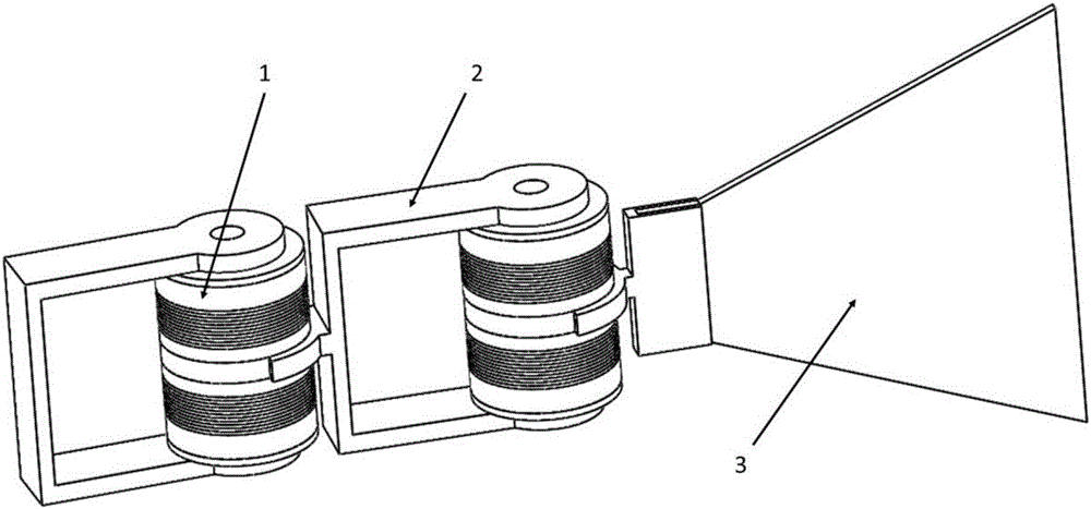
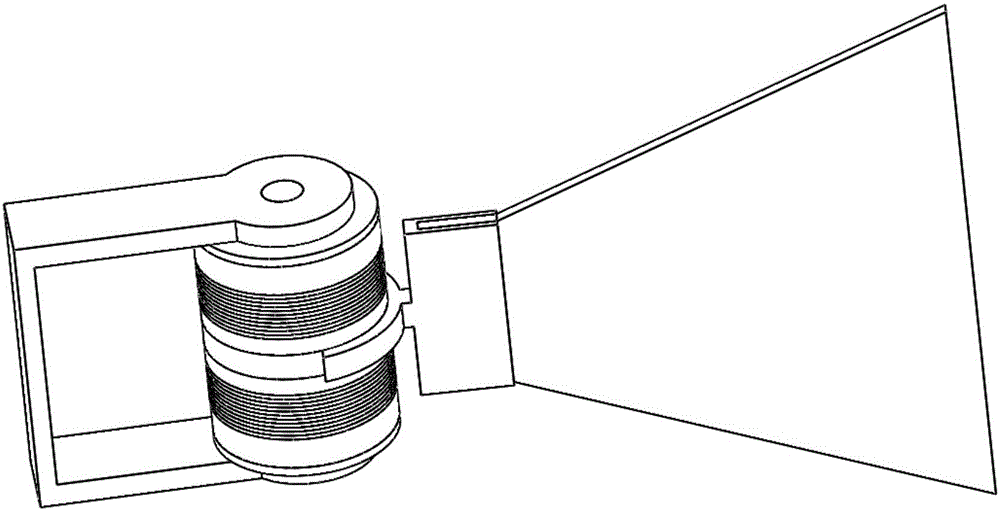
[0018] Taking the stiffness controllable underwater bionic propulsion device with two or more variable stiffness systems as an example, figure 1 It is a schematic diagram of the structure contained in the stiffness-controllable underwater bionic propulsion device of the present invention, such as figure 1 As shown, the bionic propulsion device with controllable stiffness is composed of a bionic fish tail fin 3 and several variable stiffness systems, and each variable stiffness system includes: a variable stiffness joint 1 and a joint connection frame 2 . in:

[0019] In the variable stiffness system, both ends of the variable stiffness joint are connected to the end of the joint connecting frame, and the front end of the...


PUM


Abstract

The invention discloses an underwater bionic propelling device with controllable rigidity. The underwater bionic propelling device with the controllable rigidity comprises a bionic propelling device body, variable-rigidity joints, joint connecting frameworks and a bionic fish tail fin, wherein the bionic propelling device body is composed of two or more variable-rigidity systems; each variable-rigidity system is composed of one variable-rigidity joint and one joint connecting framework; and the joint connecting framework in each variable-rigidity system is rotationally connected with a movable part in the middle of the variable-rigidity joint of the front system so that swinging of the underwater bionic propelling device can be achieved. The variable-rigidity joints change the magnetic field intensity by changing the current of magnetic induction coils, and accordingly the joint rigidity is changed. By means of the underwater bionic propelling device with the controllable rigidity, while a robot carries out different tasks in the same environment, the rigidity of the robot can be adjusted, and the optimal propelling performance of the tasks is achieved; the rigidity of the robot can also be changed in complicated environments so that the environmental adaptability can be improved; and meanwhile, in a traveling cycle, the joint rigidity of the bionic propelling device can be changed so that the propelling performance can be improved and the optimal propelling state can be achieved.

Description

technical field [0001] The invention belongs to the technical field of bionic robots, and in particular relates to an underwater bionic propulsion device with controllable stiffness, which can control the stiffness change of the bionic propulsion device of an underwater machine in real time, thereby improving the propulsion performance. Background technique [0002] Robot technology is a modern science and technology integrating bionics, mechanism science, materials science, control technology, mechatronics technology, sensing technology and artificial intelligence technology. It is an important manifestation of the country's industrial development level and scientific and technological strength, especially in military has strong applicability. The research on bionic submarines has the advantages of strong mobility, low noise, and is difficult to identify in the biological environment. Compared with traditional conventional naval weapons, it is more economical, sudden, decep...

Claims


Application Information

Patent Timeline
Patent Type & Authority Applications(China)
IPC IPC(8): B63H1/36H02K33/18H02N2/00
CPCB63H1/36H02K33/18H02N2/0005
Inventor 张世武杨懿琨王二龙李卫华孙帅帅
Owner UNIV OF SCI & TECH OF CHINA
Learn More