
Method for introducing fuel into a combustion chamber of an internal combustion engine with intake manifold injection and direct injection

A technology for intake pipes and combustion chambers, applied to internal combustion piston engines, combustion engines, fuel injection control, etc., can solve problems such as driver power loss, deterioration of exhaust emission values, and damage to individual components, and achieve good power and good emission values Effect

Pending Publication Date: 2017-02-01
ROBERT BOSCH GMBH
View PDF19 Cites 3 Cited by
  • Summary
  • Abstract
  • Description
  • Claims
  • Application Information

AI Technical Summary

Problems solved by technology

[0004] However, deviations in the fuel-air mixture (due to, for example, incorrect fuel dosing) generally lead both to worsening of the exhaust emission values ​​and, possibly, to a perceived power loss for the driver
Likewise, a so-called rich flameout can result, for example due to an excessively high fuel quantity, which can lead to damage to individual components of the internal combustion engine.

Method used


Image

  • Method for introducing fuel into a combustion chamber of an internal combustion engine with intake manifold injection and direct injection
  • Method for introducing fuel into a combustion chamber of an internal combustion engine with intake manifold injection and direct injection
  • Method for introducing fuel into a combustion chamber of an internal combustion engine with intake manifold injection and direct injection

Examples


Embodiment Construction

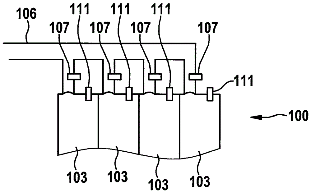
[0029] Figure 1a An internal combustion engine 100 is shown schematically and in simplified form, which can be used for the method according to the invention. Internal combustion engine 100 has, for example, four combustion chambers 103 and an intake manifold 106 , which is connected to each combustion chamber 103 .

[0030] In this case, the intake pipe 106 has a fuel injector 107 for each combustion chamber 103 which is arranged in the section of the respective intake pipe immediately before the combustion chamber. The fuel injector 107 is therefore useful for intake manifold injection. Furthermore, each combustion chamber 103 has a fuel injector 111 for direct injection.

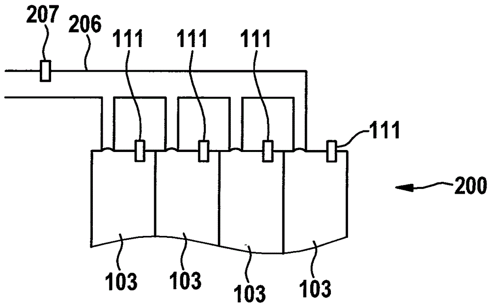
[0031] exist Figure 1b A further internal combustion engine 200 is shown schematically and in simplified form, which can be used for the method according to the invention. Internal combustion engine 100 has, for example, four combustion chambers 103 and an intake manifold 206 , which is connected to ...


PUM


Abstract

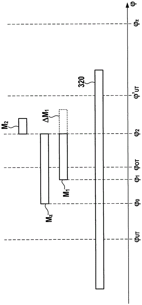
The invention relates to a method for introducing fuel into a combustion chamber of an internal combustion engine with intake manifold injection and direct injection, wherein a first fuel quantity (M1), which is discharged by means of intake manifold injection and can be introduced into the combustion chamber, is solved. If the first fuel quantity (M1) does not exceed a target fuel quantity (MZ) to be introduced into the combustion chamber by means of intake manifold injection, a second fuel quantity (M2) corresponding to a difference between the target fuel quantity (MZ) and the first fuel quantity (M1) is solved and is predetermined for the direct injection for introduction into the combustion chamber.

Description

technical field [0001] The invention relates to a method for introducing fuel into a combustion chamber of an internal combustion engine with intake manifold injection and direct injection, as well as a computing unit and a computer program for its execution. Background technique [0002] A possible method for fuel injection in gasoline engines is intake manifold injection (SRE), which is gradually being replaced by direct injection (DI). The latter method leads to a significantly better fuel distribution in the combustion chamber and thus a better power yield at lower fuel consumption, for example at moderate partial loads, whereas the first method, for example at small Based on the mixture formation, the load is advantageous in terms of fuel consumption. [0003] There are also gasoline engines with a combination of port injection and direct injection (so-called dual systems). In view of increasingly stringent emission requirements or emission limit values, this is preci...

Claims


Application Information

Patent Timeline
Patent Type & Authority Applications(China)
IPC IPC(8): F02D41/30F02D41/40
CPCF02D41/3094F02D41/402F02D2200/02F02D2200/04F02D41/10F02D41/107F02D41/221F02D41/401F02D2250/12Y02T10/40
Inventor O.阿本罗特A.布劳
Owner ROBERT BOSCH GMBH
Learn More