
Method for operating an internal combustion engine suitable for operation with gaseous and liquid fuels

a technology of liquid fuel and internal combustion engine, which is applied in the direction of engine starters, machines/engines, electric control, etc., can solve the problems of reducing starting comfort, and achieve good emission values

Inactive Publication Date: 2012-06-07
DAIMLER AG
View PDF8 Cites 4 Cited by
  • Summary
  • Abstract
  • Description
  • Claims
  • Application Information

AI Technical Summary

Benefits of technology

[0006]The start-stop mode results in a reduction of the fuel consumption of the internal combustion engine and therefore in particularly low emissions, in particular in lower carbon dioxide emissions. In the start-stop mode, the internal combustion engine is switched off when drive power is not required. This provides an improved method for operating an internal combustion engine for gaseous and liquid fuels. The liquid fuel may be in particular a gasoline-type fuel.
[0009]This provides accordingly for a fast start-up of the internal combustion engine, as it is common in an internal combustion engine which injects liquid fuel directly into the combustion chambers of internal combustion engines. In addition, the liquid fuel in the injector is regularly replaced if the stop of the internal combustion engine is followed by a start, even if the internal combustion engine is basically operated with a gaseous fuel, for example compressed natural gas (CNG). This further allows for a periodic functional check and diagnosis of the direct injection system for liquid fuel.
[0010]It has further been found to be advantageous if, when a stop of the internal combustion engine is followed by a start in the start-stop mode, gaseous fuel is introduced into the intake duct of the cylinder during an induction stroke following a single injection of liquid fuel into the combustion chamber of at least one cylinder. This means that liquid fuel is preferably injected only once, and then the respective cylinder is once again operated with gaseous fuel after starting. As the internal combustion engine is already at operating temperature at a start following a stop in the start-stop mode, no wall film formation is to be expected in the injection of liquid fuel, so that the injection of liquid fuel is accompanied by good emission values.

Problems solved by technology

This is based on the finding that the direct introduction of gaseous fuel into the combustion chamber in the start-stop mode results in a reduced starting comfort.

Method used


Image

  • Method for operating an internal combustion engine suitable for operation with gaseous and liquid fuels

Examples


Embodiment Construction

[0014]An internal combustion engine (not shown in the drawing) for a motor vehicle can be operated with gaseous and liquid fuel, for example compressed natural gas (CNG) and gasoline. For the introduction of the gas into an intake duct, the internal combustion engine is provided with a gas injector. There is further provided a liquid fuel injector by means of which liquid fuel is directly injected into the combustion chamber of each cylinder. The internal combustion engine comprises a control unit for a start-stop mode of operation.

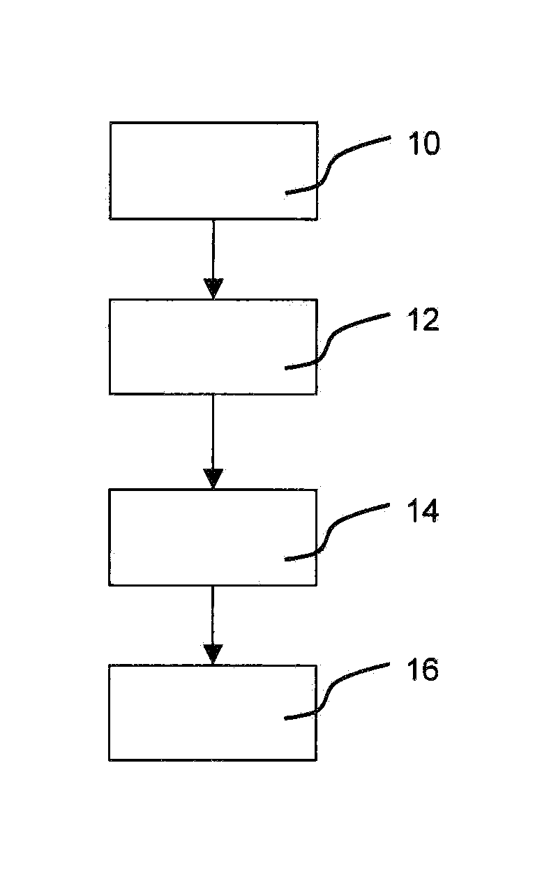
[0015]In the start-stop mode, a stop 10, for example at a traffic light or a railway crossing, is followed by an injection 12 of liquid fuel into the combustion chamber of a least one cylinder of the internal combustion engine. The combustion chamber is filled with air at this stage. Due to the preceding stop 10, the piston of the cylinder is in the area of the bottom dead center before the compression stroke. The starter effects a compression stroke of t...


PUM


Abstract

In a method for operating an internal combustion engine designed for operation with gaseous or liquid fuel, wherein gaseous fuel is introduced into an intake duct upstream of a combustion chamber of the internal combustion engine and liquid fuel is directly injected into the combustion chamber, the internal combustion engine is operated in a start-stop mode, wherein for starting the engine liquid fuel is injected into the combustion chamber of at least one cylinder so as to start the engine after shut-down with the first compression stroke of the internal combustion engine whereupon gaseous fuel is introduced into the intake duct for the second and all following engine strokes.

Description

[0001]This is a Continuation-In-Part application of pending international patent application PCT / EP2010 / 003689 filed Jun. 18, 2010 and claiming the priority of German patent application 10 2009 033 861.6 filed Jul. 16, 2009.BACKGROUND OF THE INVENTION[0002]The invention relates to a method for operating an internal combustion engine for gaseous and liquid fuels, wherein the gaseous fuel is introduced into an engine intake duct upstream of a combustion chambers of the internal combustion engine. When the internal combustion engine is operated with the liquid fuel, the liquid fuel is directly injected into the combustion chambers of the engine.[0003]DE 10 2006 049 242 A1 relates to an internal combustion engine which can be operated with gaseous and liquid fuel. For this purpose, an induction pipe of the internal combustion engine is fitted with at least one fuel injector for each cylinder, by means of which natural gas can be blown into the induction duct of each cylinder. Each cylin...

Claims


Application Information

Patent Timeline
Patent Type & Authority Applications(United States)
IPC IPC(8): F02D41/06
CPCF02D17/04F02D19/0647F02D19/081F02D41/0025F02D41/0027F02D19/0689F02D41/065F02N11/0814F02N19/00Y02T10/36F02D41/042Y02T10/30
Inventor WUNDERLICH, KLAUS
Owner DAIMLER AG
Learn More