
Method for correcting the deviation of the actual injection quantity from the nominal injection quantity caused by the pump

A technology of injection quantity and deviation, which is applied in the direction of fuel injection device, fuel injection control, electrical control, etc., and can solve the problems of no MAR synchronous pump supply, no injection synchronization, etc.

Active Publication Date: 2021-09-03
ROBERT BOSCH GMBH
View PDF5 Cites 0 Cited by
  • Summary
  • Abstract
  • Description
  • Claims
  • Application Information

AI Technical Summary

Problems solved by technology

[0006] But there are also situations where there is neither injection synchronization nor MAR synchronization pump feed

Method used


Image

  • Method for correcting the deviation of the actual injection quantity from the nominal injection quantity caused by the pump
  • Method for correcting the deviation of the actual injection quantity from the nominal injection quantity caused by the pump
  • Method for correcting the deviation of the actual injection quantity from the nominal injection quantity caused by the pump

Examples


Embodiment Construction

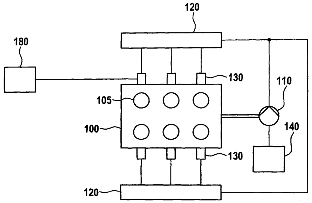
[0026] figure 1 An internal combustion engine 100 with a common rail system is schematically shown, which is suitable for carrying out the method according to the invention in a preferred configuration. For example, internal combustion engine 100 includes six combustion chambers or associated cylinders 105 . Each combustion chamber 105 is assigned a fuel injector 130 , which in turn is connected to a high-pressure accumulator 120 , via which fuel injector the high-pressure accumulator is supplied with fuel. Although two high-voltage accumulators 120 are shown, they are interconnected and thus function as a single high-voltage accumulator 120 . However, the embodiment shown is common in common rail systems in general.

[0027] Furthermore, high-pressure accumulator 120 is supplied with fuel from fuel tank 140 via high-pressure pump 110 . The high-pressure pump 110 is designed here as a piston pump with two pistons. Each piston achieves two feed strokes in one pump revolutio...


PUM


Abstract

The invention relates to a method for distributing an injection quantity of fuel into at least one combustion chamber of an internal combustion engine by means of a fuel injector, wherein the fuel injector is supplied with fuel by a high-pressure accumulator, which is supplied with fuel by a high-pressure pump , in which the pump working gap position of the high-pressure pump is taken into account when dispensing the injection quantity.

Description

technical field [0001] The invention relates to a method for distributing injection quantities of fuel into combustion chambers, in particular for reducing injection quantity deviations between individual combustion chambers of an internal combustion engine. Background technique [0002] In a common rail system, the injection characteristics of the fuel injectors are under the influence of the delivery characteristics of the high-pressure pump. For this reason it is usually expedient to select the speed ratio between the pump rotational speed and the motor rotational speed in such a way that the fuel injectors of all cylinders or associated combustion chambers see the same working gap position of the high-pressure pump. This ensures minimal cylinder-block-injection quantity deviations and thus smooth engine operation. In this case it is a single-injection synchronized pump supply. [0003] In some cases the speed ratio so selected does not satisfy the volume balance. This...

Claims


Application Information

Patent Timeline
Patent Type & Authority Patents(China)
IPC IPC(8): F02D41/40
CPCF02D41/0085F02D41/3845F02D41/40F02D2200/0602F02M39/00Y02T10/40
Inventor S·特兰
Owner ROBERT BOSCH GMBH
Learn More