
Method for operating a compressor arrangement, and a compressor arrangement

a compressor arrangement and compressor technology, applied in the direction of piston pumps, pump control, non-positive displacement fluid engines, etc., can solve the problems of affecting the efficiency of the compressor arrangement, the mesh connection state is particularly difficult to operate, and the partial load range is also accompanied by additionally undesirable emissions. , to achieve the effect of good efficiency and good emission values

Inactive Publication Date: 2010-08-26
SIEMENS AG
View PDF8 Cites 0 Cited by
  • Summary
  • Abstract
  • Description
  • Claims
  • Application Information

AI Technical Summary

Benefits of technology

[0006]Starting from the previously described difficulties, the invention has made it its task to create methods for operating compressor stations, and to create a compressor station which even in the case of fluctuating load has both good efficiency and good emission values in all load ranges.
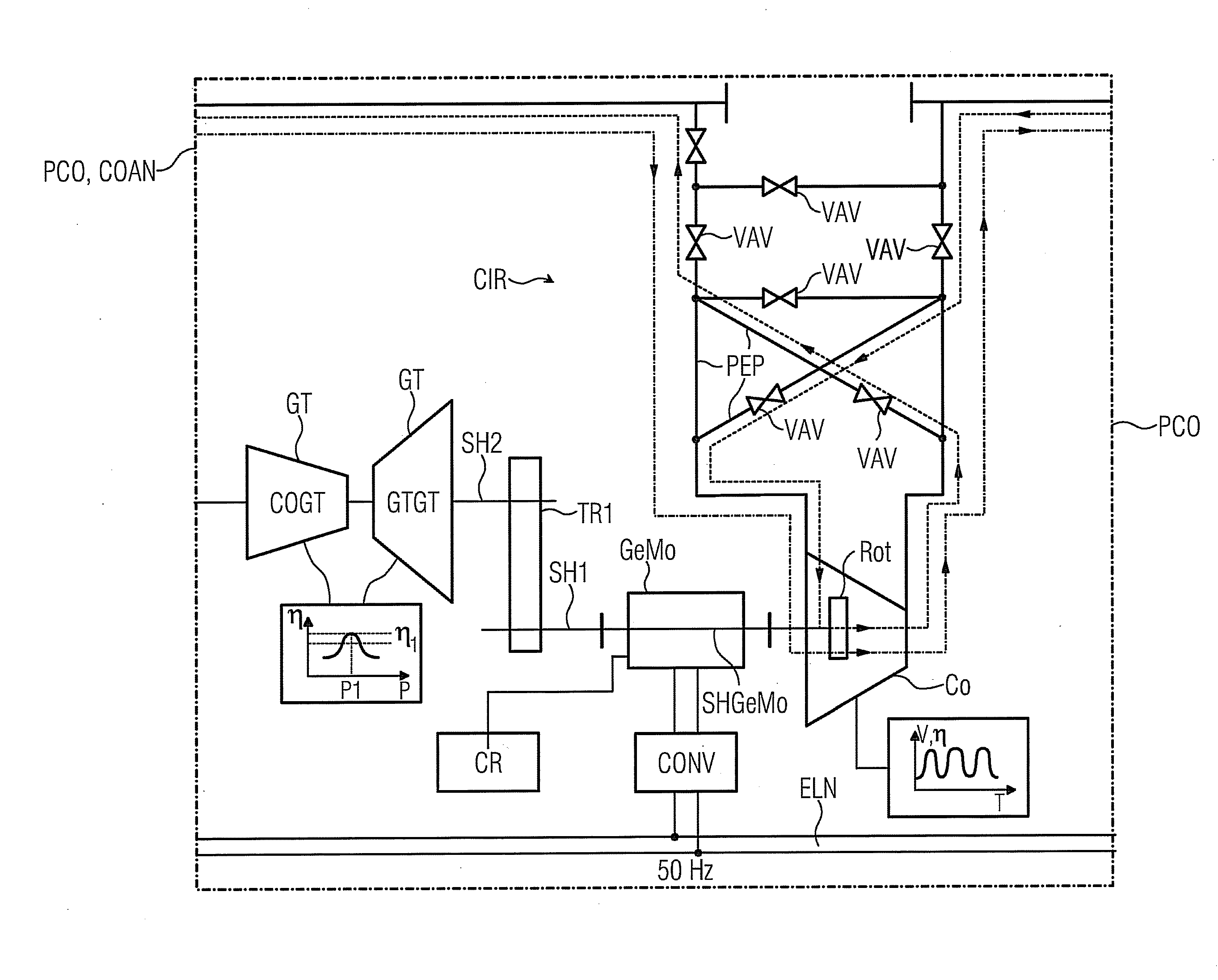
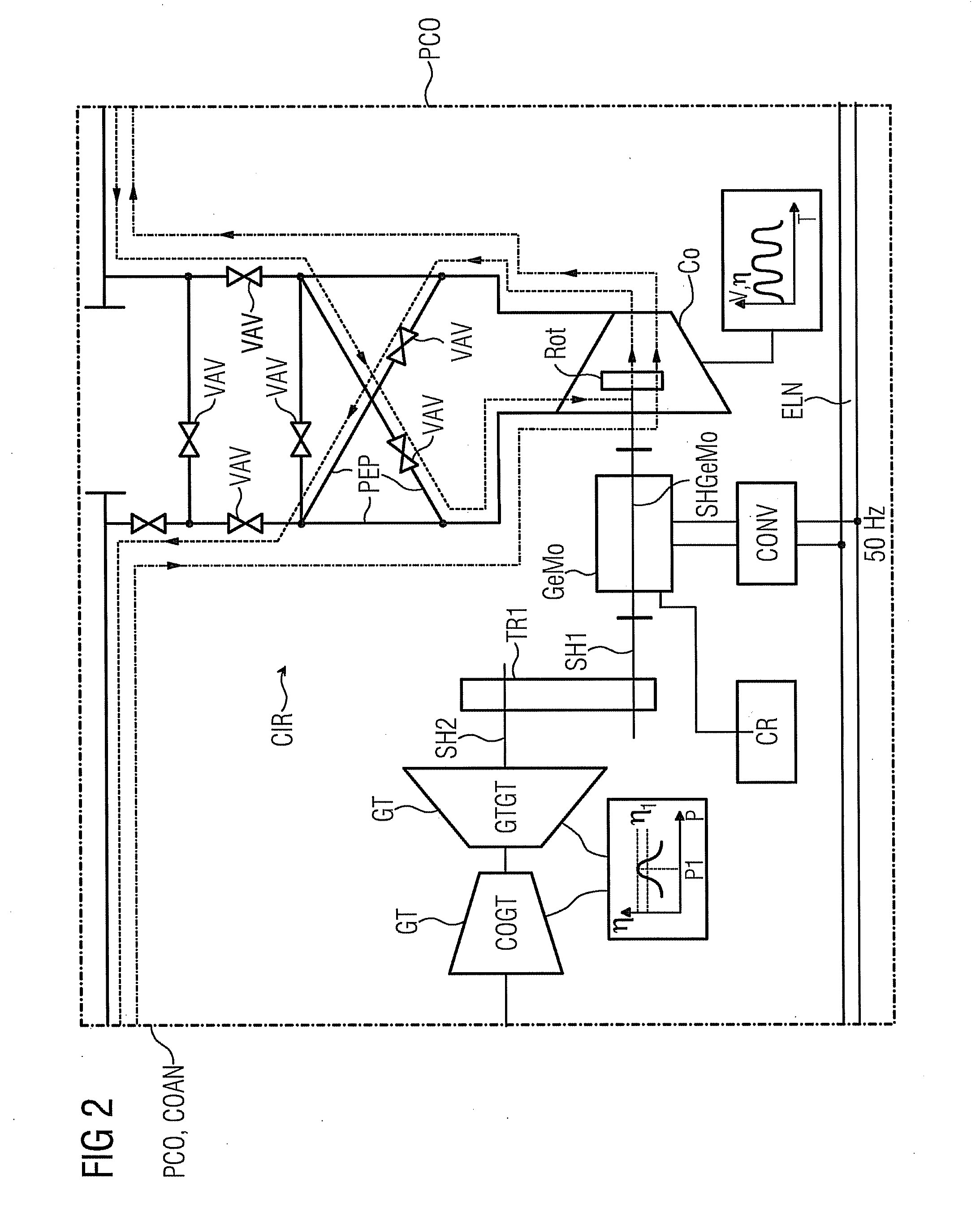
[0008]As a result of the variable use according to the invention of the electrodynamic machine, the turbine, which is preferably designed as a gas turbine, succeeds in constantly operating closer to the efficiency maximum in the partial load range or within the range of an overload than is the case with conventional plants. The entire plant is preferably constantly operated very close to the efficiency maximum of the turbine or gas turbine so that both the fuel consumption and the pollutant emission are minimal.
[0010]The electrodynamic machine, during operation as a motor, is supplied from an electricity supply system, to which the power which is generated during operation as a generator is re-supplied, preferably via the interposition of a frequency converter. In this way, on the one hand the operator saves on fuel for the operation, and on the other hand saves on expenditure for emissions licenses. Furthermore, possibly when utilizing the non-optimum operating ranges of the turbine, this arrangement can cope with higher peak loads on account of the switching-in capability of the electrodynamic machine as a motor. A gas turbine, which for example can be operated between 4 and 8 MW, in combination with an electrodynamic machine according to the invention which has 4 MW output, can operate a compressor with an output of between 0 and 12 MW of driving power. If in this case the turbine is operated only with an optimum efficiency of for example 7 MW, the latitude is still between 3 MW and 11 MW of driving power.
[0014]So undesirable delays do not occur within the scope of maintenance operations on the compressor, this is preferably designed in a barrel-type construction and is not provided with a continuous shaft so that the electrodynamic machine can be attached only on one side of the compressor. The electrodynamic machine in this case is preferably equipped with a continuous shaft so that either the turbine is connected directly to the free end, or a torque-transmitting operational arrangement is preferably coupled to a free end of the independent turbine shaft. This second shaft arrangement has particular advantages with regard to the use of standard modules and brings along an expedient shaft dynamic.

Problems solved by technology

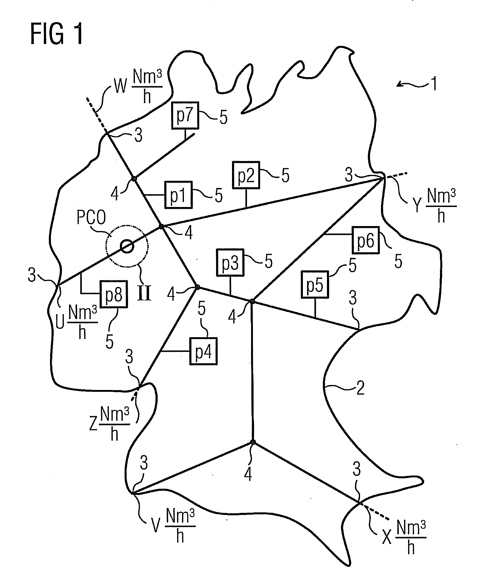
A task which is related to the previously described problems is the distribution of natural gas by means of a network of pipelines which in its mesh-connected state is particularly difficult to operate in the case of simultaneously irregular distribution of the consumers.
The gas requirement at the consumer stations in this case is fluctuating, however, in such a way that the requirement frequently borders upon the technical limits and, calling upon all capacities, has to be unconditionally prevented, in such a way that pressures fall below contractually permissible limits.
This happens at times, however, despite determined use of so-called pipeline compressor stations and costly trials by means of mathematical simulations to allow the gas network to optimally “breathe” at the right moment.
The compressors of the compressor arrangements are regularly driven by means of gas turbines which achieve their optimum efficiency under full load, that is to say at 100% nominal output, and in the partial load range or in the case of overload regularly feature dramatic efficiency losses.
Furthermore, the partial load range is also accompanied by additionally undesirable emissions and a disproportionally high curtailment of the service life.

Method used


Image

  • Method for operating a compressor arrangement, and a compressor arrangement
  • Method for operating a compressor arrangement, and a compressor arrangement
  • Method for operating a compressor arrangement, and a compressor arrangement

Examples


Embodiment Construction

[0019]FIG. 1 shows a gas distribution network 1 which extends over a specified territory 2 and has various interfaces 3 to adjacent regions. At the interfaces, standard volumetric flows U, V, W, X, Y, Z flow into or out of the gas distribution network 1 of the territory 2 at specified pressure levels in each case. The pressure level can lie for example between 50 and 100 bar. In the case of the gas distribution network 1 it is a mesh-connected network with a plurality of junction points 4. Supplier tappings 5, at which gas of a specified individual pressure p1-p10 is tapped from the gas distribution network 1, are located at various sites. At the same time it is possible that storage feeds into the network take place. The pressure p1-p10 can fluctuate within contractually stipulated limits which in most cases are stipulated between 50 and 100 bar. At various points in the gas distribution network 1 a pipeline compressor station PCO or compressor arrangement COAN is arranged in each ...


PUM


Abstract

A method is provided for operating a compressor arrangement, particularly a pipeline compressor station, wherein the compressor arrangement has a turbine and a compressor in a torque-transferring connection. Previous systems work over long periods with poor efficiency when the turbine is working under a partial load. A solution is provided which includes an electrodynamic machine having a torque-transferring connection to the compressor, wherein the turbine has a maximum efficiency at a specific output, and when the compressor output is below the specific output, the electrodynamic machine is operated as a generator, and when the compressor output is above the specific output, the electrodynamic machine is operated as a motor.

Description

CROSS REFERENCE TO RELATED APPLICATIONS[0001]This application is the US National Stage of International Application No. PCT / EP2007 / 064236, filed Dec. 19, 2007 and claims the benefit thereof. The International Application claims the benefits of European Patent Office application No. 07000271.2 EP filed Jan. 8, 2007, both of the applications are incorporated by reference herein in their entirety.FIELD OF INVENTION[0002]The invention refers to a method for operating a compressor arrangement, especially a pipeline compressor station, which compressor arrangement has a turbine and a compressor which are in torque-transmitting communication, wherein an electrodynamic machine is in torque-transmitting communication with the compressor, wherein the turbine with a specified first turbine output has an efficiency maximum, wherein in the case of a compressor output below the first turbine output the electrodynamic machine is operated as a generator, and in the case of a compressor output above...

Claims


Application Information

Patent Timeline
Patent Type & Authority Applications(United States)
IPC IPC(8): F04B49/06F02C6/04F04B35/04
CPCF01D15/08F04D25/06F04D25/02F01D15/10
Inventor SCHWULERA, ULRICH
Owner SIEMENS AG
Learn More