
Three-dimensional finite element model trimming method capable of embodying manufacture geometric defects

A geometric defect and finite element technology, applied in the field of three-dimensional finite element model adjustment, can solve problems such as difficult to consider manufacturing geometric defects

Active Publication Date: 2017-02-01
DALIAN UNIV OF TECH
View PDF3 Cites 5 Cited by
  • Summary
  • Abstract
  • Description
  • Claims
  • Application Information

AI Technical Summary

Problems solved by technology

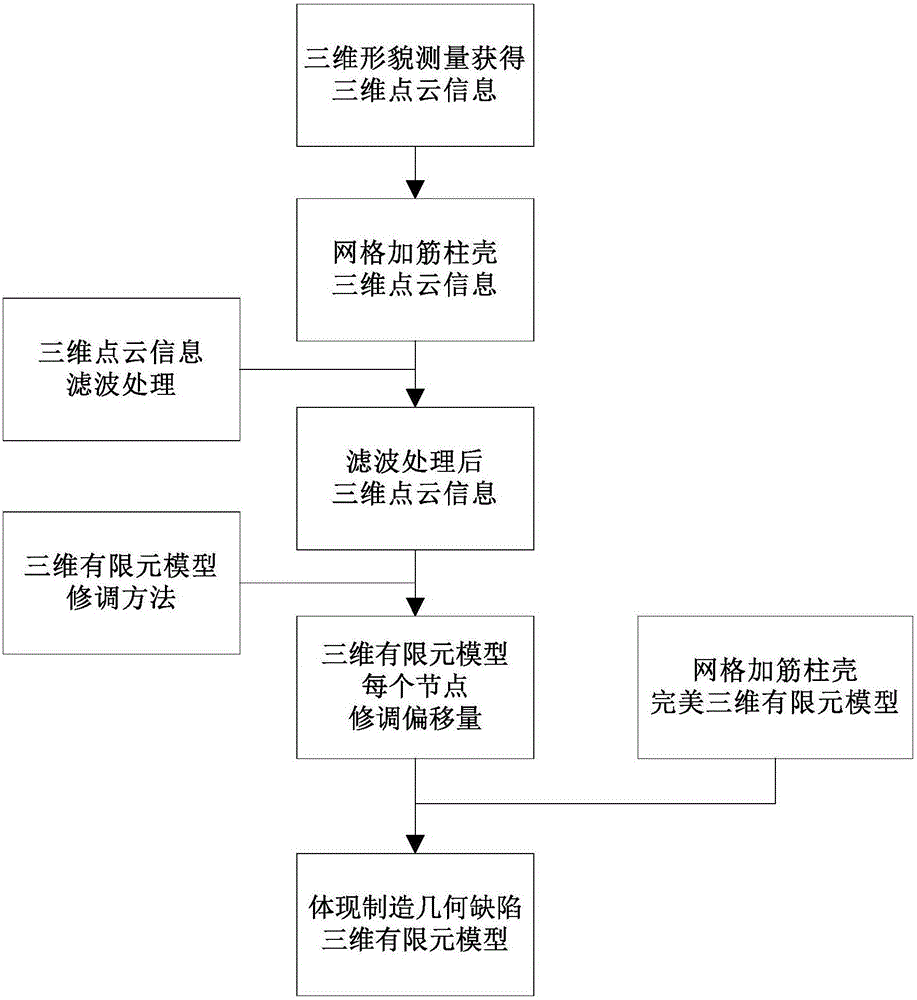
[0005] The present invention mainly solves the problem that the existing numerical analysis model of the axially compressed grid-reinforced shell structure is difficult to consider the measured manufacturing geometric defects, and proposes a three-dimensional finite element model modification method for the purpose of reflecting the manufacturing geometric defects. On the basis of the element model, through the actual measurement of 3D point cloud information, based on the principle of node-by-point spatial neighborhood correspondence, the interpolation technology is used to modify the node coordinates in the perfect 3D finite element model, and then obtain the 3D finite element model based on real manufacturing geometric defects. Meta-model, in order to achieve the purpose of accurately predicting the ultimate bearing capacity of the structure

Method used


Image

  • Three-dimensional finite element model trimming method capable of embodying manufacture geometric defects
  • Three-dimensional finite element model trimming method capable of embodying manufacture geometric defects
  • Three-dimensional finite element model trimming method capable of embodying manufacture geometric defects

Examples


Embodiment Construction

[0041] In order to make the method problem solved by the present invention, the method scheme adopted and the method effect achieved clearer, the present invention will be further described in detail below in conjunction with the accompanying drawings and embodiments. It should be understood that the specific embodiments described here are only used to explain the present invention, but not to limit the present invention. In addition, it should be noted that, for the convenience of description, only parts related to the present invention are shown in the drawings but not all content.

[0042] figure 1 It is an implementation flowchart of a three-dimensional finite element model modification method for the purpose of reflecting manufacturing geometric defects provided by the embodiment of the present invention. Such as figure 1 As shown, a three-dimensional finite element model modification method for the purpose of reflecting manufacturing geometric defects provided by an em...


PUM


Abstract

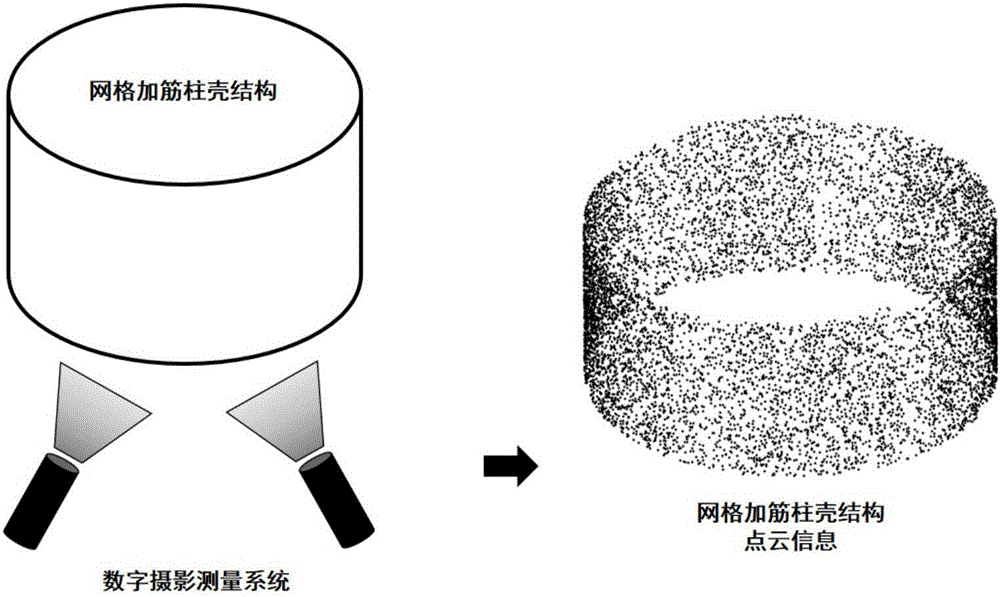
The invention belongs to the technical field of the design of the main force-bearing component of an aerospace structure, and relates to a three-dimensional finite element model trimming method capable of embodying manufacture geometric defects. The method comprises the following steps of: 1) adopting an optical measurement method to carry out measurement to obtain three-dimensional point cloud information; 2) carrying out filtering processing on the three-dimensional point cloud information to eliminate noise; 3) establishing a perfect structure three-dimensional finite element model which does not consider the three-dimensional point cloud information; and 4) on the basis of the three-dimensional point cloud information, or after the obtained three-dimensional point cloud information is subjected to amplification and reduction processing, adopting an interpolation method to trim the perfect structure three-dimensional finite element model, and embodying the manufacture geometric defects. By use of the method, the authenticity of a finite element prediction model can be enhanced, furthermore, the accuracy of finite element prediction can be improved, meanwhile, an existing finite element model can be guaranteed to be fully utilized to realize adaptive defect amplitude scaling and position selection, a workload is extremely low, and the method is expected to become one of the key technologies of finite element model correction in an aerospace field.

Description

technical field [0001] The invention belongs to the technical field of design of main load-bearing components of aerospace structures, and relates to a three-dimensional finite element model modification method for the purpose of reflecting manufacturing geometric defects. Background technique [0002] It is well known that axially compressed thin-walled cylindrical shell structures are very sensitive to initial geometrical imperfections. In the 1940s, in the rocket technology research group led by von Karman, Mr. Qian Xuesen’s very important research work was the research on the stability reduction factor of thin-walled light shells, and found that the reduction factor varies with the structure form and size. And change. Generally speaking, the larger the "diameter-thickness ratio" (radius R of the shell divided by the equivalent thickness t of the shell) of the axially compressed shell structure, the higher the defect sensitivity and the smaller the reduction factor. The...

Claims


Application Information

Patent Timeline
IPC IPC(8): G06F17/50G06T19/20
CPCG06F30/15G06F30/23G06T19/20G06T2219/2016Y02T90/00
Inventor 王博郝鹏毕祥军杜凯繁任明法黄诚蒋亮亮
Owner DALIAN UNIV OF TECH
Learn More