
A linear transmission method of electronic current transformer signal

A technology of current transformers and transmission methods, applied in non-electrical signal transmission systems, signal transmission systems, instruments, etc.

Inactive Publication Date: 2019-06-14
SHANDONG UNIV OF TECH
View PDF5 Cites 0 Cited by
  • Summary
  • Abstract
  • Description
  • Claims
  • Application Information

AI Technical Summary

Problems solved by technology

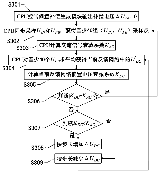
In the above method, since it is not necessary to artificially inject other signals, it is the simplest and most direct method to directly use the DC bias voltage signal as a reference signal for optical signal attenuation. The complete "luminous power P-drive current I" relationship is not a linear relationship, resulting in the attenuation of the DC bias voltage when this method is used K DC attenuation of the AC signal under test K AC is not consistent, that is K DC ≠ K AC

Method used


Image

  • A linear transmission method of electronic current transformer signal
  • A linear transmission method of electronic current transformer signal
  • A linear transmission method of electronic current transformer signal

Examples


Embodiment Construction

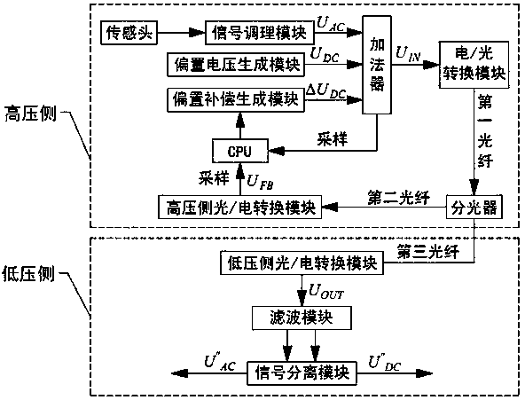
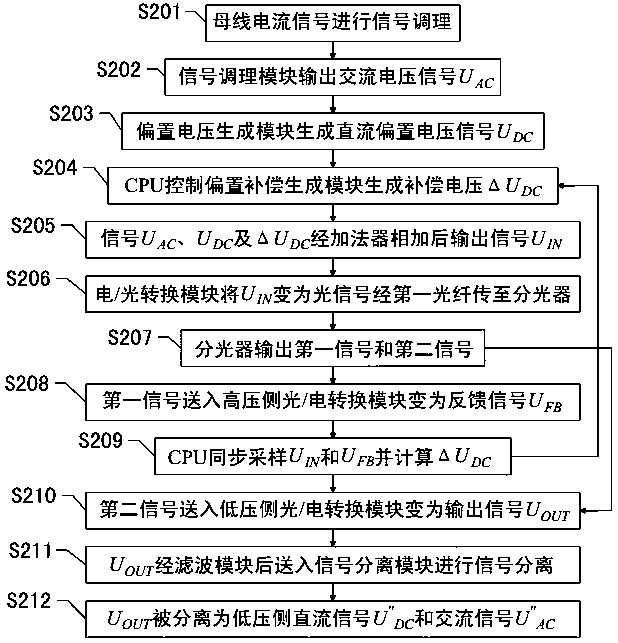
[0057] Figure 1~5 It is the best embodiment of the linear transmission method of the electronic current transformer signal, below in conjunction with the attached Figure 1~5 The specific implementation manner of the linear transmission method of the electronic current transformer signal of the present invention will be further described in detail.

[0058] refer to figure 1 :

[0059] figure 1 It is a structural block diagram of a linear transmission device for electronic current transformer signals, including a sensor head, a signal conditioning module, a bias voltage generation module, a bias compensation generation module, an adder, an electrical / optical conversion module, an optical splitter, and a high-voltage side light / electrical conversion module, CPU, first optical fiber, second optical fiber, third optical fiber, low-voltage side optical / electrical conversion module, filter module and signal separation module; the sensor head is connected with the signal cond...


PUM


Abstract

The invention discloses an electronic current transformer signal linear transmission device and method and belongs to the field of electrical measurement. The device comprises a sensing head, a signal conditioning module, a bias voltage generation module, a bias compensation generation module, an adder, an electro / optical conversion module, a splitter, a high-voltage side optical / electrical conversion module, a CPU, a first optical fiber, a second optical fiber, a third optical fiber, a low voltage side optical / electrical conversion module, a filtering module and a signal separation module. The sensing head outputs a bus current signal to the signal conditioning module, the signal conditioning module carries out signal conditioning, the signal conditioning module outputs an alternating voltage signal UAC in proportion to the magnitude of the bus current, the bias voltage generation module produces a direct current bias voltage signal UDC, and the CPU computes and controls the bias compensation generation module so that offset voltage delta UDC is produced. The device and method have the advantages of low cost and simple test processes and realize equality of attenuation of bias voltage applied to a high voltage side and attenuation of an alternating current signal transmitted practically.

Description

technical field [0001] The invention relates to a linear transmission method for electronic current transformer signals, which belongs to the field of electric measurement. Background technique [0002] Current transformer is an important equipment for power system production, measurement and protection. With the continuous improvement of power system voltage level and capacity, the traditional electromagnetic current transformer can no longer meet the actual production needs. Therefore, the new electronic current transformer Transformers have gradually become an ideal substitute for traditional electromagnetic current transformers due to their advantages such as good insulation performance, strong anti-interference ability, small size, low cost, wide measurement dynamic range, and high sensitivity. [0003] At present, the high-voltage side signal conversion methods applied to electronic current transformers mainly include voltage-frequency (V / F) method, analog-to-digital (...

Claims


Application Information

Patent Timeline
Patent Type & Authority Patents(China)
IPC IPC(8): G08C23/06
CPCG08C23/06
Inventor 王玮徐丙垠
Owner SHANDONG UNIV OF TECH
Learn More