
A controller for electric machine

A motor controller and controller technology, applied in the direction of motor control, control system, AC motor deceleration device, etc., can solve vehicle stability problems, affect vehicle stability and other problems, and achieve the effect of reducing drag torque

Inactive Publication Date: 2017-02-01
PROTEAN ELECTRIC LIMITED
View PDF5 Cites 2 Cited by
  • Summary
  • Abstract
  • Description
  • Claims
  • Application Information

AI Technical Summary

Problems solved by technology

[0014] However, if the inverter used to supply current to the motor is placed in a first non-switching mode, wherein the inverter is used to place the motor in an open circuit configuration, and the rotor of the motor is spinning at high speed, if Back EMF is higher than the battery voltage, current will flow from the motor into the battery, causing such as Figure 7 Indicated braking torques that may create vehicle stability problems
[0015] Alternatively, if the inverter used to supply current to the motor used to place the motor in a short circuit configuration is placed in a second non-switching mode, the induction in the motor coil windings caused by the back EMF current can cause Figure 8 Drag torque shown, which may also affect vehicle stability

Method used


Image

  • A controller for electric machine
  • A controller for electric machine
  • A controller for electric machine

Examples


Embodiment Construction

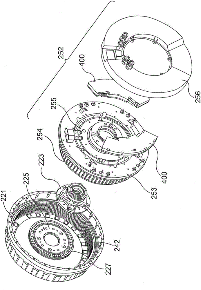
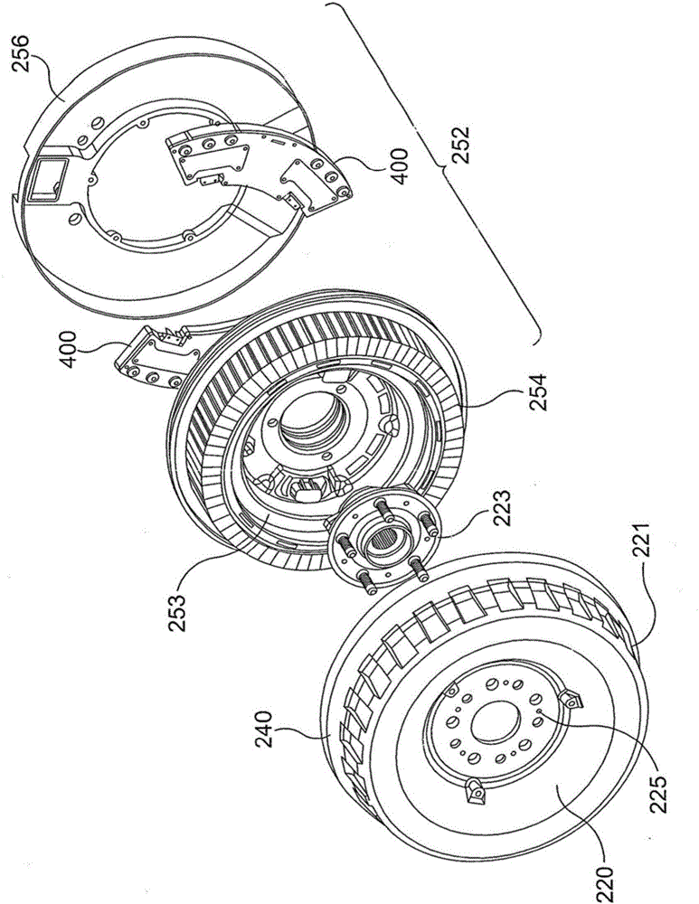
[0030] The illustrated embodiment of the invention is a controller for controlling the structure and operation of an inverter used to control current flow in the coil windings of an electric motor. For the purposes of this example, the electric motor is used in the wheels of the vehicle, but the electric motor could be located anywhere within the vehicle. The type of electric machine described has a set of coils as part of a stator mounted to the vehicle radially surrounded by a rotor carrying a set of magnets mounted to the wheels. For the avoidance of doubt, various aspects of the invention are equally applicable to generators having the same arrangement. Thus, the definition of electric machine is intended to include generators. Furthermore, some aspects of the present invention are applicable to configurations having a rotor mounted centrally within radially surrounding coils. As will be appreciated by those skilled in the art, the invention is also applicable for use wi...


PUM


Abstract

A controller for placing an electric motor in a disabled condition is disclosed. The controller cocomprises means arranged to place an inverter in a first configuration if a rotor of the electric motor is rotating above or equal to a predetermined velocity, and means arranged to place the inverter in a second configuration if the rotor of the electric motor is rotating below the predetermined velocity, wherein the first configuration of the inverter allows current generated by the electric motor to be redirected back to the electric motor and the second configuration of the inverter allows voltage generated by the electric motor to be switched across a battery.

Description

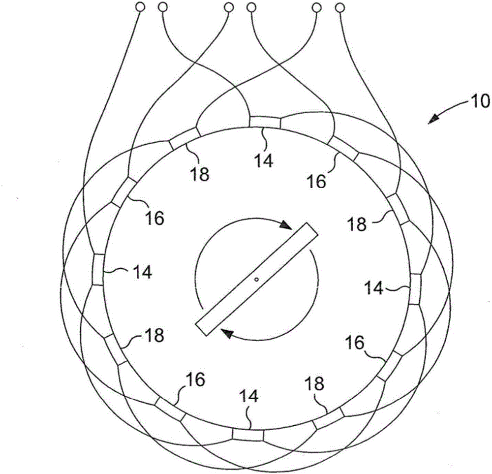
technical field [0001] The invention relates to a controller, especially a motor controller. Background technique [0002] Motors work on the principle that current-carrying wires will be stressed in the presence of a magnetic field. When the current-carrying wire is placed perpendicular to the magnetic field, the force on the current-carrying wire is proportional to the flux density of the magnetic field. Typically, the force on the current-carrying wires in an electric motor develops as a rotational torque. [0003] Three-phase electric machines typically include three coil sets, where each coil set is arranged to generate a magnetic field associated with one of the three phases of the alternating voltage. [0004] In order to increase the number of magnetic poles formed in the motor, each coil set usually has a plurality of coil sub-sets distributed around the motor, the sub-coils are driven to generate a rotating magnetic field. [0005] For example, figure 1 A typic...

Claims


Application Information

Patent Timeline
Patent Type & Authority Applications(China)
IPC IPC(8): H02K11/33
CPCH02P29/00H02P3/22
Inventor 理查德·伯克
Owner PROTEAN ELECTRIC LIMITED
Learn More