Valve and cooling system of friction clutch for wet running

A friction clutch and cooling system technology, which is applied in the field of friction clutch valves and cooling systems for wet operation, can solve the problem of high drag torque and achieve the effect of small drag torque and high cooling power

Active Publication Date: 2015-02-11
SCHAEFFLER TECH AG & CO KG
View PDF6 Cites 0 Cited by
  • Summary
  • Abstract
  • Description
  • Claims
  • Application Information

AI Technical Summary

Problems solved by technology

However, this setting has the disadvantage that the drag torque occurring in the disengaged state of the friction clutch is very high due to the (high) shear viscosity in the cooling bath

Method used


Image

  • Valve and cooling system of friction clutch for wet running
  • Valve and cooling system of friction clutch for wet running
  • Valve and cooling system of friction clutch for wet running

Examples


Embodiment Construction

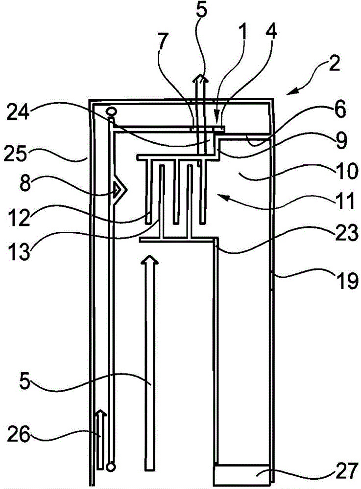
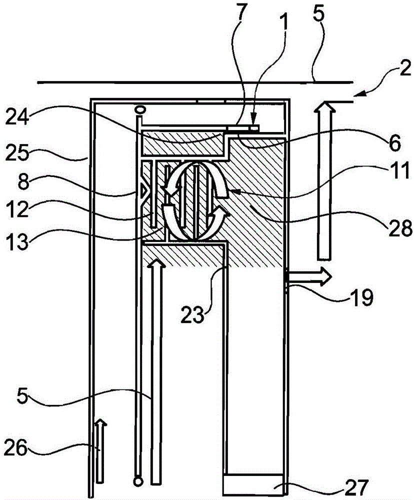
[0038] figure 1 A cooling system 2 is shown in which a valve 1 is provided, which is composed of an actuating piston 8 with a first outlet 7 and a blocking element 6 as a section of an outer disk cage 9 . A gap seal 24 is arranged between the actuating piston 8 and the blocking element 9 , which only allows a small portion of the cooling fluid 5 to flow through. Arranged in the outer disk cage 9 is a first friction partner 12 which corresponds to the second friction partner 13 in the inner disk cage 23 and forms the disk package 11 . The disc pack 11 can be closed by operating the piston 8, as follows in figure 2 shown in the . Furthermore, there is a second outlet 19 for the cooling fluid 5 , which is arranged below the disk pack 11 and above the output shaft 27 . In the first state shown here, almost no flow flows through the second outlet 19 . The actuating piston 8 is actuated by an actuating fluid 26 , which moves the actuating piston 8 in the direction of the disk p...


PUM


Abstract

The invention relates to a valve for a cooling system for a wet-running friction clutch, comprising at least the following components: at least one valve element that can be axially moved from an open state of the friction clutch to a closed state of the friction clutch and that is used for cooling fluid, and at least one corresponding locking element capable of moving relative to the valve element, and at least one first outlet for the cooling fluid, wherein the at least one first outlet is processed in the at least one valve element, and the valve is arranged in such a way that when the friction clutch is switched from the open state to the closed state, the at least one first outlet, by means of a relative movement between the valve element and the locking element, is closed. With the valve and cooling system proposed here, it is possible to combine the advantages of spray-cooled and bath-cooled friction clutches.

Description

technical field [0001] The invention relates to a valve for a cooling system and a cooling system for a wet-running friction clutch, in particular an injection-cooled friction clutch. Background technique [0002] Various settings for cooling friction clutches are known from the prior art. For example, the disk pack of a friction clutch is operated in a cooling bath, through which the frictional heat is dissipated. This setting has the advantage that a very large amount of heat can be dissipated and thus the mass of the friction clutch can be kept low. However, this setting has the disadvantage that the drag torque occurring in the disengaged state of the friction clutch is very high due to the (high) shear viscosity in the cooling bath. In contrast, the provision of an injection-cooled friction clutch has the advantage that no (high) drag torque is applied here, since no cooling pool is formed. However, the heat dissipation of an injection-cooled friction clutch is much ...

Claims


Application Information

Patent Timeline
IPC IPC(8): F16D13/72
CPCF16D13/72F16D25/0638F16D25/123F16D2300/0214
Inventor M·屈恩勒
Owner SCHAEFFLER TECH AG & CO KG
Why Eureka
Try Eureka