Method and system for correcting IQ and TIADC joint frequency distortion
A frequency distortion and frequency technology, applied in the field of analog-to-digital conversion, can solve problems such as image frequency interference and achieve good compensation effects
- Summary
- Abstract
- Description
- Claims
- Application Information
AI Technical Summary
Problems solved by technology
Method used
Image
Examples
Embodiment 1
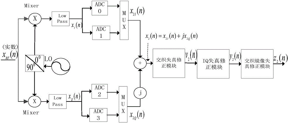
[0040] Such as figure 1 as shown, figure 1 It is a schematic diagram of the structure of the down-conversion and time-interleaved analog-to-digital converter (IQ-TIC). The input signal enters the I branch and the Q branch respectively, and then enters the 2-channel TIADCs after being output by the I branch and the Q branch. Each channel uses the same The high-speed input signal is sampled at different sampling times (difference time between adjacent channels), and the output signal is finally combined to realize the analog-to-digital conversion of signal down-conversion and high-speed sampling.
[0041] Among them, x(n) outputs x after I / Q down-conversion I (n) and x Q (n), the output after TIADC is x 2I (n) and x 2Q (n), then the total output of the system is x 2 (n)=x 2I (n)+x2Q (n).
[0042] For output signal x 2 (n) The analysis of the first Nyquist zone of the spectrum found that there are four kinds of spectrum, which are the ideal components of linear distortion...
Embodiment 2
[0052] In this embodiment, a specific experiment has been carried out according to the method of embodiment 1. The frequency spectrum position of the receiver input signal used in the experiment is -0.3, 0.3, specifically as Figure 9 mentioned. The frequency used for down-conversion is 0.5pi, and the sampling frequency of TIADC is N=2. Such as Figure 10 As shown, there are four kinds of frequency components in the output signal of the IQ-TIC structure, and the spectral positions (normalized frequency) are -0.8, -0.2, 0.2, 0.8 respectively, which are respectively located at the image distortion position of TIADC and the ideal linear distortion position Component position, IQ distortion position, TIADC distortion position. Figure 11 , Figure 12 , Figure 13 They are the modified spectrograms of TIADC distortion, IQ distortion and TIADC image distortion respectively. Depend on Figure 11 , Figure 12 , Figure 13 It can be seen that after the correction method is corr...
Embodiment 3
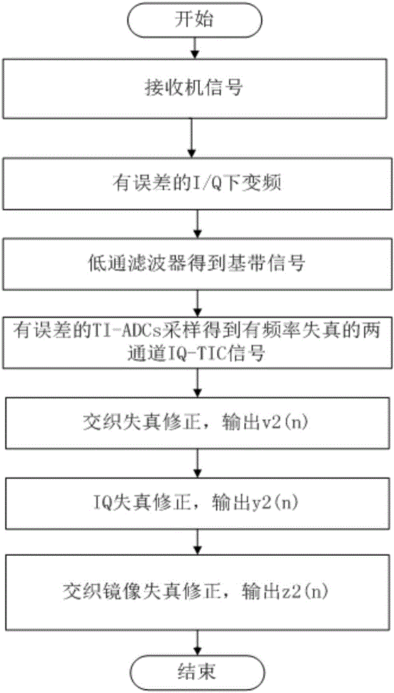
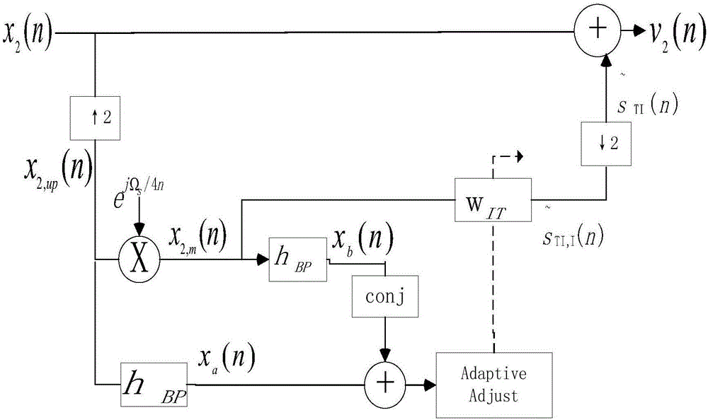
[0055] On the basis of Embodiment 1, the present invention provides a system applying the method of Embodiment 1, the structure of the system is as follows figure 1 As shown, it includes an interleaving distortion correction module, an IQ distortion correction module and an interleaving image distortion correction module, wherein the interleaving distortion correction module corrects TIADC frequency distortion based on the method of step (1); the IQ distortion correction module is based on the method of step (2) The IQ frequency distortion is corrected; the interleaved image distortion correction module corrects the TIADC image distortion based on the method in step (3).
PUM
 Abstract
Description
Claims
Application Information
 - R&D
- Intellectual Property
- Life Sciences
- Materials
- Tech Scout
- Unparalleled Data Quality
- Higher Quality Content
- 60% Fewer Hallucinations
Browse by: Latest US Patents, China's latest patents, Technical Efficacy Thesaurus, Application Domain, Technology Topic, Popular Technical Reports.
© 2025 PatSnap. All rights reserved.Legal|Privacy policy|Modern Slavery Act Transparency Statement|Sitemap|About US| Contact US: help@patsnap.com


