
Smart visual holder system and realization method thereof

A technology of intelligent vision and cloud platform, which is applied in the direction of closed-circuit television system, TV system components, TV, etc., and can solve the problems of single function and low degree of intelligence

Inactive Publication Date: 2017-02-01
INST OF AUTOMATION CHINESE ACAD OF SCI +1
View PDF5 Cites 25 Cited by
  • Summary
  • Abstract
  • Description
  • Claims
  • Application Information

AI Technical Summary

Problems solved by technology

[0006] The purpose of the present invention is to provide an intelligent visual pan-tilt system to solve the technical problems of low intelligence and single function of the existing system

Method used


Image

  • Smart visual holder system and realization method thereof
  • Smart visual holder system and realization method thereof
  • Smart visual holder system and realization method thereof

Examples


Embodiment Construction

[0031] Preferred embodiments of the present invention are described below with reference to the accompanying drawings. Those skilled in the art should understand that these embodiments are only used to explain the technical principles of the present invention, and are not intended to limit the protection scope of the present invention.

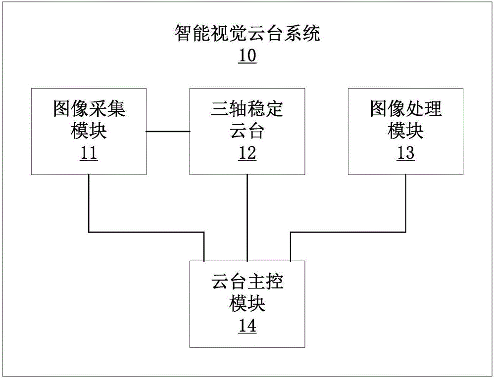
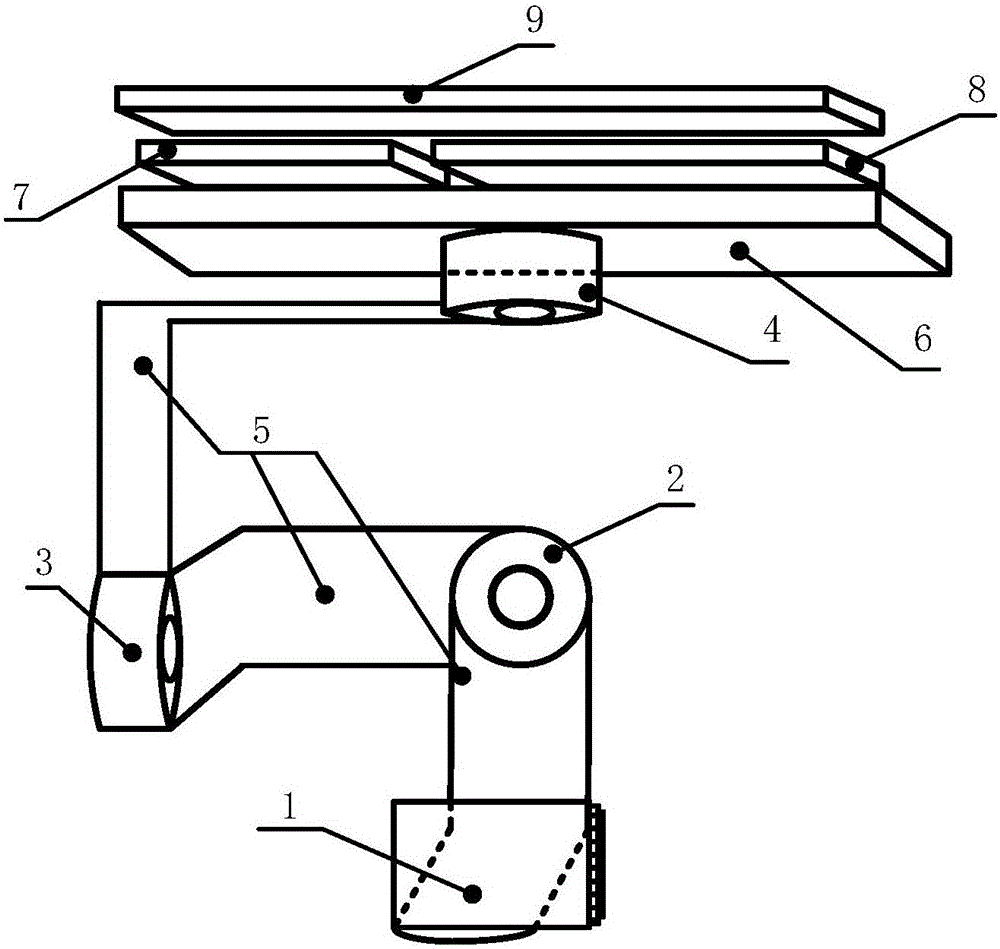
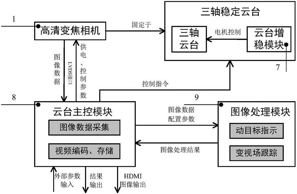
[0032] In order to solve the technical problems of low intelligence and single function of the existing system, an embodiment of the present invention provides an intelligent visual pan-tilt system. Such as figure 1 As shown, the system 10 may include: an image acquisition module 11 , a three-axis stabilized gimbal 12 , a gimbal main control module 14 and an image processing module 13 . Wherein, the image acquisition module 11 is used for acquiring high-speed high-definition sequence images, and sending the acquired images to the pan / tilt main control module 14 . The three-axis stabilized pan / tilt 12 is used to control the posture of the ima...


PUM


Abstract

The invention relates to a smart visual holder system and a realization method thereof. The system comprises an image collection module which is used for collecting high-speed high-definition sequence images and sending the collected images to a holder master control module; a tri-axial stabilizing holder which is used for controlling a posture of the image collection module; the holder master control module which interacts with the image collection module, the tri-axial stabilizing holder and an image processing module and is used for carrying out video coding and storage on the images collected by the image collection module; and the image processing module which is used for carrying out format conversion on the images received by the holder master control module from the image collection module and processing the images, thereby finishing visual target tracking under moving target indication and a variable field of view, and feeding back a processing result to the holder master control module. The technical problem that an existing system is low in intelligentization degree and single in function is solved. Two intelligent visual functions of moving target indication and variable field of view target continuous tracking are integrated, thereby facilitating use.

Description

technical field [0001] The invention relates to the technical field of pan-tilt motor control and image processing, in particular to an intelligent vision pan-tilt system and its implementation method. Background technique [0002] Modern drones are usually positioned as "flying smart cameras", and their core technologies also revolve around this purpose, mainly including autopilots, intelligent vision gimbals, and image transmission modules. Among them, the intelligent visual gimbal, as the core unit, has become a hot spot for competition among major drone manufacturers. [0003] In layman's terms, a smart gimbal is a three-axis stabilized gimbal that mounts a smart camera. In order to counteract the influence of body shaking or vibration, aerial photography gimbals usually need to stabilize the camera in the three axes of horizontal, roll, and pitch; in order to enable the drone to perform certain operations intelligently, it is necessary to use intelligent visual images ...

Claims


Application Information

Patent Timeline
IPC IPC(8): H04N7/18H04N5/232
CPCH04N7/18H04N23/66
Inventor 李书晓朱承飞常红星廖兴池
Owner INST OF AUTOMATION CHINESE ACAD OF SCI
Learn More