
Panoramic video polygon sampling method and panoramic video polygon sampling method

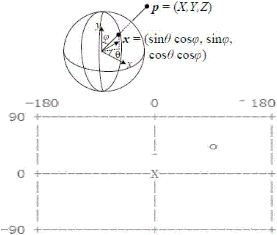
A panoramic video and polygon technology, applied in the field of video coding, can solve the problems of sampling redundancy, rectangles do not have complete adjacency, uneven distribution, etc., to reduce the number of sampling points, avoid sampling structure redundancy, and have strong flexibility. Effect

Active Publication Date: 2017-02-01
SHANGHAI GMT DIGITAL TECH
View PDF3 Cites 13 Cited by
  • Summary
  • Abstract
  • Description
  • Claims
  • Application Information

AI Technical Summary

Problems solved by technology

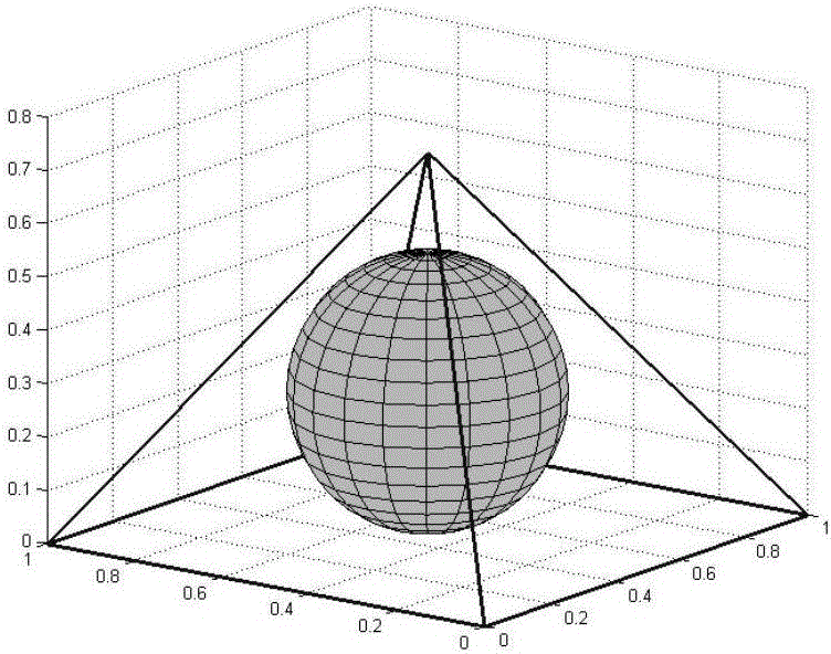
The distribution of sampling points of hexahedron sampling on the spherical surface is also uneven, there is still a large redundancy, and the content of the rectangle does not have complete adjacency
[0009] To sum up, the main disadvantages of the existing panoramic video sampling methods are that there is a large redundancy in the sampling structure and the resulting rectangle does not have complete adjacency of content.
The uneven distribution of sampling points on the spherical surface will not only bring sampling redundancy, but also bring inconvenience to video quality evaluation, because the spherical area corresponding to the final sampling point is different, so the distortion of each sampling point has a great impact on video quality. The impact is also different. When calculating the quality loss of the panoramic video after some processing, such as compression and decompression, it must be considered that the importance of each sampling point is different.

Method used


Image

  • Panoramic video polygon sampling method and panoramic video polygon sampling method
  • Panoramic video polygon sampling method and panoramic video polygon sampling method
  • Panoramic video polygon sampling method and panoramic video polygon sampling method

Examples


Embodiment 1

[0061] Such as Figure 6 Shown is one image of a panoramic video represented by a latitude and longitude map with a resolution of 4096×2048. In a specific embodiment of the present invention, the panoramic video is a color video with three components. Assuming that the color components used are RGB, RGB is still used to represent the color of each sampling point after sampling. Assume that the requirements for spatial resolution are the same for the three components, all of which are N=1024 and M=2048, and the requirements for quantization precision are also the same for each component, all of which are quantized to 256 levels. Then for each component, repeat steps 1 to 4 as follows:

[0062] Step 1: Divide the spherical surface into 1024 circular surfaces with equally spaced parallels. Denote these annular surfaces as O i , i=0,1,...,1023. Will O i The latitude corresponding to the central latitude line of is denoted as θ i , θ i =|i-511.5|×π / 1024. Will O i The area ...

Embodiment 2

[0070] Such as Figure 6 Shown is one image of a panoramic video represented by a latitude and longitude map with a resolution of 4096×2048. In a specific embodiment of the present invention, the panoramic video is a color video with three components. Assuming that the color component used is YCbCr, and the sampling ratio is 4:4:4, YCbCr is still used to represent the color of each sampling point after sampling. Assume that the requirements for spatial resolution are N=1024 and M=2048 for the Y component, and N=512 and M=1024 for the Cb and Cr components, and the quantization precision requirements are the same for each component, and they are all quantized to 256 levels.

[0071] For the Y component, the following steps are performed:

[0072] Step 1: Divide the spherical surface into 1024 circular surfaces with equally spaced parallels. Denote these annular surfaces as O i , i=0,1,...,1023. Will O i The latitude corresponding to the central latitude line of is denoted a...


PUM


Abstract

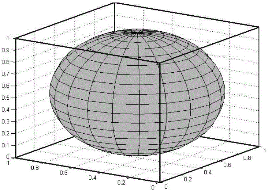
The invention discloses a panoramic video polygon sampling method and a panoramic video polygon sampling method. The method comprises steps: according to space resolution requirements, uniformly-spaced latitudes are used for dividing a spherical surface into N ring curved surfaces; according to space resolution requirements, L ring curved surfaces located near the equator are uniformly divided into M areas along the equator direction, and each area is corresponding to one sampling point; the other ring curved surfaces are uniformly divided into Mi parts along the equator direction according to an arithmetic sequence, the closer the ring curved surface is to the equator, the larger Mi is, and each part is corresponding to one sampling point; and the calculated average value of light in each area on the spherical surface serves as a sampling value of sampling points corresponding to the area. Sampling points on the spherical surface meet the characteristic that many sampling points are near the equator and few sampling points are at two poles, redundancy of the sampling structure is avoided, and in the same space resolution condition, the number of sampling points is reduced and the data amount after sampling is reduced.

Description

technical field [0001] The present invention relates to video coding technology, in particular to a panoramic video polygon sampling method and device. Background technique [0002] Panoramic video refers to all the scenes around an observation point in space, which is composed of all the light that this observation point can receive. Panoramic video can be abstracted into a sphere centered on the observation point. [0003] When using a computer to process panoramic video, it is inevitable to perform discretized spatial sampling on the panoramic video. When discretizing the spatial sampling of the panoramic video, it is necessary to ensure a certain spatial sampling density to achieve the required definition. At the same time, it is also necessary to consider that the memory of the computer is not suitable for storing data of a spherical structure, and it is necessary to arrange the sampling points on the plane in a certain way. [0004] The existing spherical sampling m...

Claims


Application Information

Patent Timeline
Patent Type & Authority Applications(China)
IPC IPC(8): H04N19/132
CPCH04N19/132
Inventor 吴成家顾晓林畅赵海武李国平滕国伟王国中
Owner SHANGHAI GMT DIGITAL TECH
Learn More