
Polishing machine for hardware machining

A polishing machine and hardware technology, applied in the field of hardware parts processing, can solve the problems of uneven rotation rate, uneven polishing, high risk, etc., and achieve the effect of improving work efficiency, increasing polishing rate, and wide application range

Inactive Publication Date: 2017-02-08
嘉兴市耀华精密金属股份有限公司
View PDF6 Cites 0 Cited by
  • Summary
  • Abstract
  • Description
  • Claims
  • Application Information

AI Technical Summary

Problems solved by technology

[0003] As we all know, in the process of metal processing, it is often necessary to polish and polish some metal pipes to be processed or processed. The existing metal pipes are generally polished by manual use of a single grinder. Such polishing The method is not only inefficient, but also has the disadvantages of high labor intensity and high risk for the operators. At the same time, during the polishing process of the pipe, after the pipe is between the polishing and the guide wheel, due to the uneven rotation rate of the pipe itself Problems, uneven polishing is prone to occur, which affects the quality of products that need to be polished, thereby increasing production costs

Method used


Image

  • Polishing machine for hardware machining
  • Polishing machine for hardware machining
  • Polishing machine for hardware machining

Examples


Embodiment

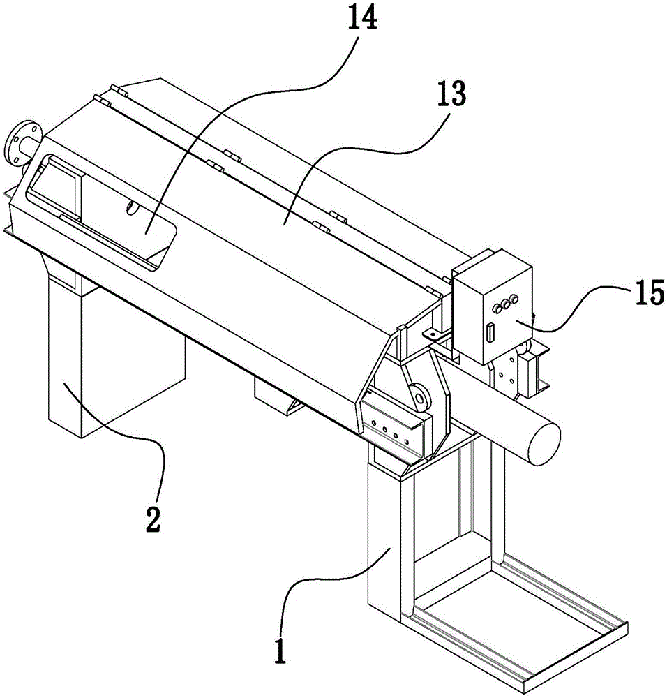
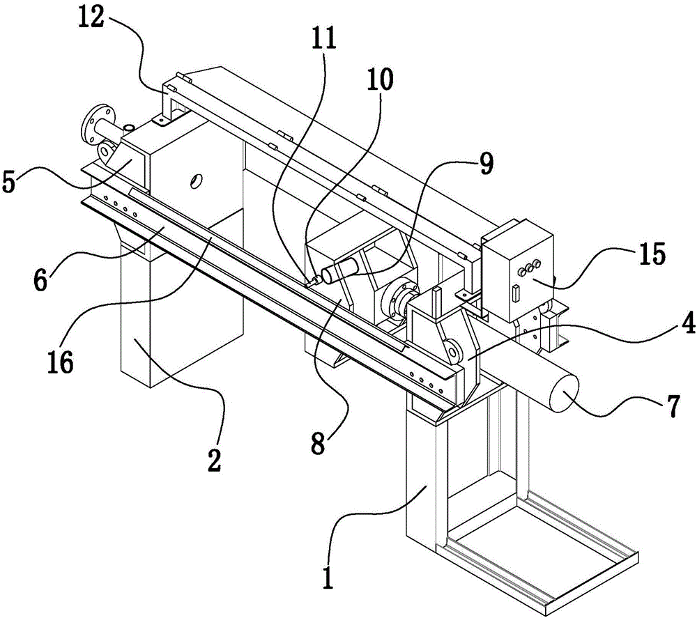
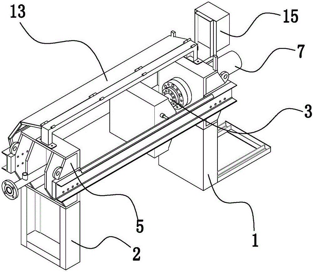
[0021] Example: such as Figure 1-3 As shown, a polishing machine for metal processing includes a front frame 1, a rear frame 2, a sliding shaft 3 and a polishing cover device; the front frame 1 and the rear frame 2 are respectively provided with a front mounting seat 4 and a rear mounting Seat 5, both sides of front mounting seat 4 and rear mounting seat 5 are fixedly provided with placing frame 6, and front mounting seat 5 is fixed with bearing 7, and one end of described sliding shaft 3 is sleeved in bearing 7, and along the bearing 7 slide back and forth, the other end of sliding shaft 3 is fixedly provided with polishing device, and polishing device is corresponding with placement frame 6 positions; Connected with an output rotating shaft 10, the output rotating shaft 10 is connected with a polishing wheel 11, and the polishing wheel 11 is located at the upper end of the placement frame 6; the front mount 4 is equipped with a driving device 15 for driving the polishing de...


PUM


Abstract

The invention relates to a polishing machine for hardware machining. The polishing machine comprises a front rack, a rear rack, a sliding shaft and a polishing cover device; the front rack is provided with a front mounting base, the rear rack is provided with a rear mounting base, containing frames are fixedly arranged on the two sides of the front mounting base and the rear mounting base, a bearing is fixedly arranged in the front mounting base, one end of the sliding shaft is sleeved with the bearing, and slides in a front-and-back manner along the bearing, the other end of the sliding shaft is fixedly provided with a polishing device, and the polishing device corresponds to the containing frames in position; and the polishing device comprises a polishing base, output rotating shafts are connected to polishing motors, polishing wheels are connected to the output rotating shafts, and the polishing wheels are located at the upper ends of the containing frames. The polishing device and the containing frames are matched in position, multiple hardware machining components can be polished at the same time, and the work efficiency is improved; and meanwhile, the polishing wheels can be detachably connected to the output rotating shafts, the size of the polishing wheels can be selected according to needs, the polishing machine is suitable for hardware of different types and specifications, and the application range is wide.

Description

technical field [0001] The invention belongs to the technical field of hardware parts processing, and in particular relates to a polishing machine for hardware processing. Background technique [0002] There are many types of hardware, such as door handles, faucets, connecting nuts and other products that are formed by metal processing. [0003] As we all know, in the process of hardware processing, it is often necessary to polish and polish some metal pipes to be processed or processed. The existing metal pipes are generally polished by manually using a single grinder to polish the surface of the metal pipe. Such polishing The method is not only inefficient, but also has the disadvantages of high labor intensity and high risk for the operators. At the same time, during the polishing process of the pipe, after the pipe is between the polishing and the guide wheel, due to the uneven rotation rate of the pipe itself The problem is that uneven polishing is prone to occur, whic...

Claims


Application Information

Patent Timeline
IPC IPC(8): B24B29/02B24B29/08B24B41/06
CPCB24B29/02B24B29/08B24B41/06
Inventor 鲁跃明
Owner 嘉兴市耀华精密金属股份有限公司
Learn More