Eureka AIR delivers breakthrough ideas for toughest innovation challenges, trusted by R&D personnel around the world.

Pipeline cutting device

A pipe cutting and pipe technology, which is applied in the field of pipe cutting devices, can solve the problems of small stress-bearing area of ​​pipes, decreased product precision, and not easy to fix, etc., to achieve the effect of ensuring work efficiency, ensuring stability, and improving cutting efficiency

Inactive Publication Date: 2017-02-08
ANHUI RUIZHIXIN INFORMATION TECH CO LTD
View PDF5 Cites 7 Cited by
  • Summary
  • Abstract
  • Description
  • Claims
  • Application Information

AI Technical Summary

Problems solved by technology

[0002] With the development of the modern mechanical processing industry, the requirements for cutting quality and precision are constantly improving, and the requirements for improving production efficiency, reducing production costs, and highly intelligent automatic cutting functions are also increasing. The development of CNC cutting machines must be To meet the requirements of the development of the modern mechanical processing industry, the existing cutting machine is not easy to fix due to the small force-bearing area of ​​the pipe, and it is easy to produce deviations during the cutting process, resulting in a decrease in the accuracy of the cut product, and the pipes are often worn after production. With high temperature, it is easy to deform the pipe when cutting

Method used


Image

  • Pipeline cutting device
  • Pipeline cutting device
  • Pipeline cutting device

Examples


Embodiment Construction

[0017] The following will clearly and completely describe the technical solutions in the embodiments of the present invention with reference to the accompanying drawings in the embodiments of the present invention. Obviously, the described embodiments are only some, not all, embodiments of the present invention. Based on the embodiments of the present invention, all other embodiments obtained by persons of ordinary skill in the art without making creative efforts belong to the protection scope of the present invention.

[0018] Implementation column 1

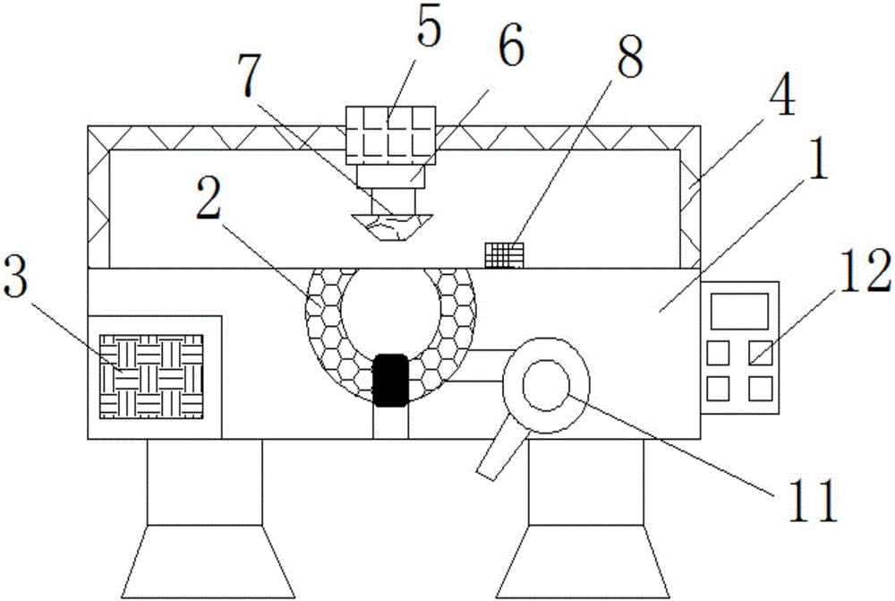
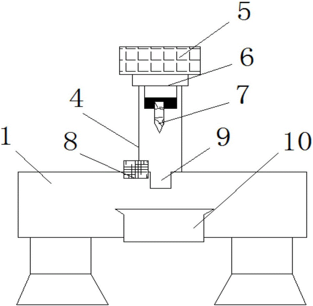
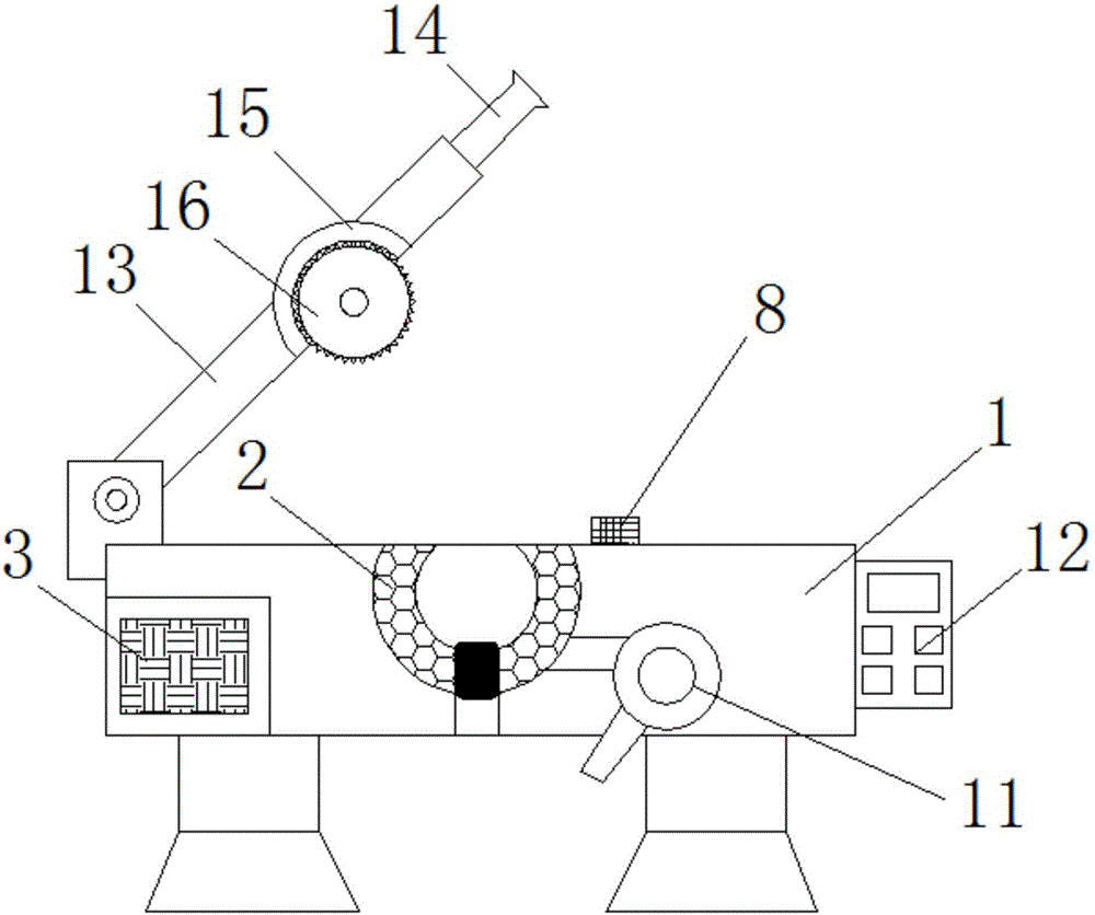
[0019] like Figure 1-2 The shown pipe cutting device includes a machine platform 1, at least four sets of outriggers are arranged symmetrically on the bottom of the machine platform 1, and rubber pads are pasted on the bottom of the outriggers, and a traction pipe is provided inside the machine platform 1 2. The inner bottom of the traction duct 2 is provided with a pulley, and the inner surface of the traction duct 2 is inla...


PUM


Abstract

The invention discloses a pipeline cutting device. The pipeline cutting device comprises a machine table. A traction pipeline is arranged in the machine table. A cold air fan is fixedly connected to one side of the traction pipeline, and an air outlet of the cold air fan stretches into the traction pipeline. A storage battery set is arranged on one side in the machine table. A support is fixedly arranged on the top of the machine table. An air cylinder body is arranged on the top of the support. The bottom of the air cylinder body is in transmission connection with a telescopic rod. The bottom end of the telescopic rod is fixedly connected with a cutting tool. A cutting groove is formed in the position, located right at the lower end of the cutting tool, of the top of the machine table, a waste storage box is arranged at the bottom of the cutting groove, a distance measuring sensor is arranged on one side of the cutting groove, and a PLC is fixedly arranged on one side of the machine table. The pipeline cutting device is reasonable in structural design, time and labor are saved, operation is convenient, functions are comprehensive, the cutting quality and the cutting efficiency are improved, and popularization is facilitated.

Description

technical field [0001] The invention belongs to the technical field of cutting devices, and in particular relates to a pipe cutting device. Background technique [0002] With the development of the modern mechanical processing industry, the requirements for cutting quality and precision are constantly improving, and the requirements for improving production efficiency, reducing production costs, and highly intelligent automatic cutting functions are also increasing. The development of CNC cutting machines must be To meet the requirements of the development of the modern mechanical processing industry, the existing cutting machine is not easy to fix due to the small force-bearing area of ​​the pipe, and it is easy to produce deviations during the cutting process, resulting in a decrease in the accuracy of the cut product, and the pipes are often worn after production. With high temperature, it is easy to deform the pipe when cutting. Contents of the invention [0003] The ...

Claims


Application Information

Patent Timeline
Patent Type & Authority Applications(China)
IPC IPC(8): B26D1/06B26D7/06B26D5/40B26D7/18B26D3/16F25D3/00B23D45/12B23D79/00B23D47/00B23Q17/00B23Q11/00
CPCB23D45/12B23D47/00B23D79/00B23Q11/00B23Q17/00B26D1/06B26D3/001B26D3/16B26D5/40B26D7/06B26D7/18F25D3/00
Inventor 吴新明李洋王永辉吴旋
Owner ANHUI RUIZHIXIN INFORMATION TECH CO LTD
Why Eureka
Eureka Blog
Learn More