An earthquake-damaged replaceable steel beam structure

A steel beam and section steel technology, applied in the field of earthquake-damaged replaceable steel beam structures, can solve the problems of difficult maintenance and replacement of steel beams and high maintenance and replacement costs, and achieve the effects of reduced transportation difficulty, low repair costs, and simple construction

Active Publication Date: 2019-11-12
HUAQIAO UNIVERSITY
View PDF10 Cites 0 Cited by
  • Summary
  • Abstract
  • Description
  • Claims
  • Application Information

AI Technical Summary

Problems solved by technology

However, due to the existence of the floor slab, it is difficult to repair and replace the steel beam after the earthquake damage or the cost of repair and replacement is still high

Method used


Image

  • An earthquake-damaged replaceable steel beam structure
  • An earthquake-damaged replaceable steel beam structure
  • An earthquake-damaged replaceable steel beam structure

Examples


Embodiment 1

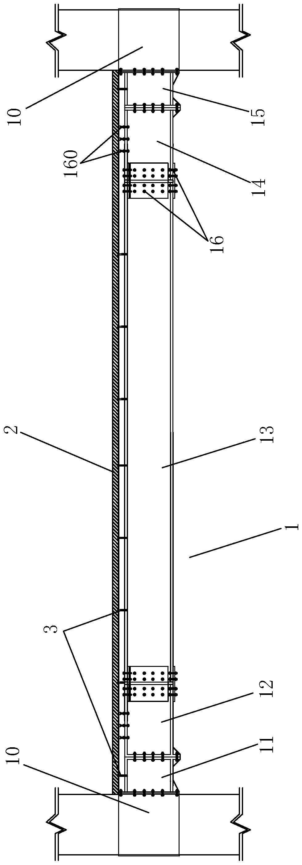
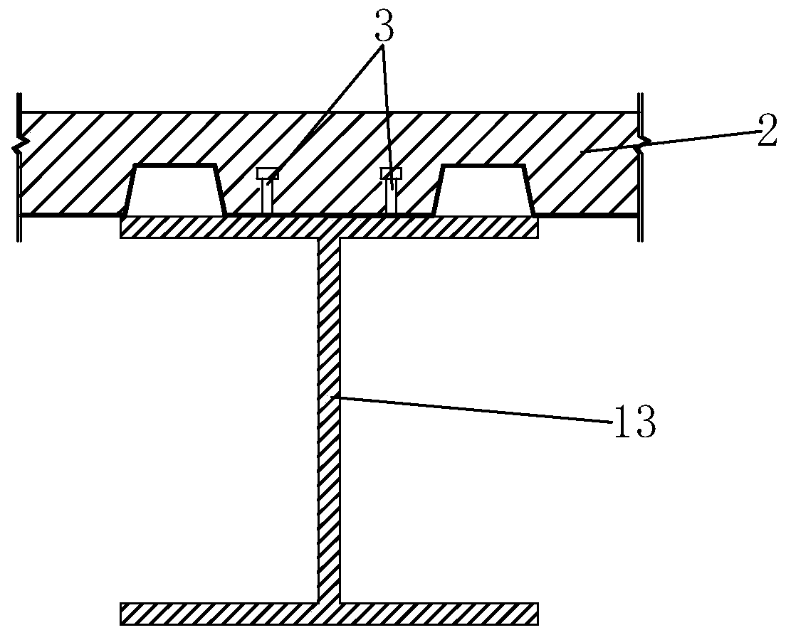
[0035] Such as figure 1 As shown, a seismically damaged replaceable steel beam structure includes a composite steel beam 1 and a composite floor 2 connected to the composite steel beam 1, and the composite steel beam 1 includes a first end steel beam connected in sequence 11. A first energy-dissipating section steel beam 12, a mid-span steel beam 13, a second energy-dissipating section steel beam 14 and a second end steel beam 15, the first end steel beam 11 and the second end The steel beams 15 are respectively connected to the end columns 10 on both sides, and the above-mentioned steel beams are all I-shaped beams, such as figure 2 As shown, the mid-span steel beam 13 is connected to the composite floor 2 through welding studs 3 . Such as Figure 5 As shown, the steel beam 12 of the first energy dissipation section and the steel beam 14 of the second energy dissipation section are both connected to the composite floor 2 through the second high-strength friction bolt 160 w...

Embodiment 2

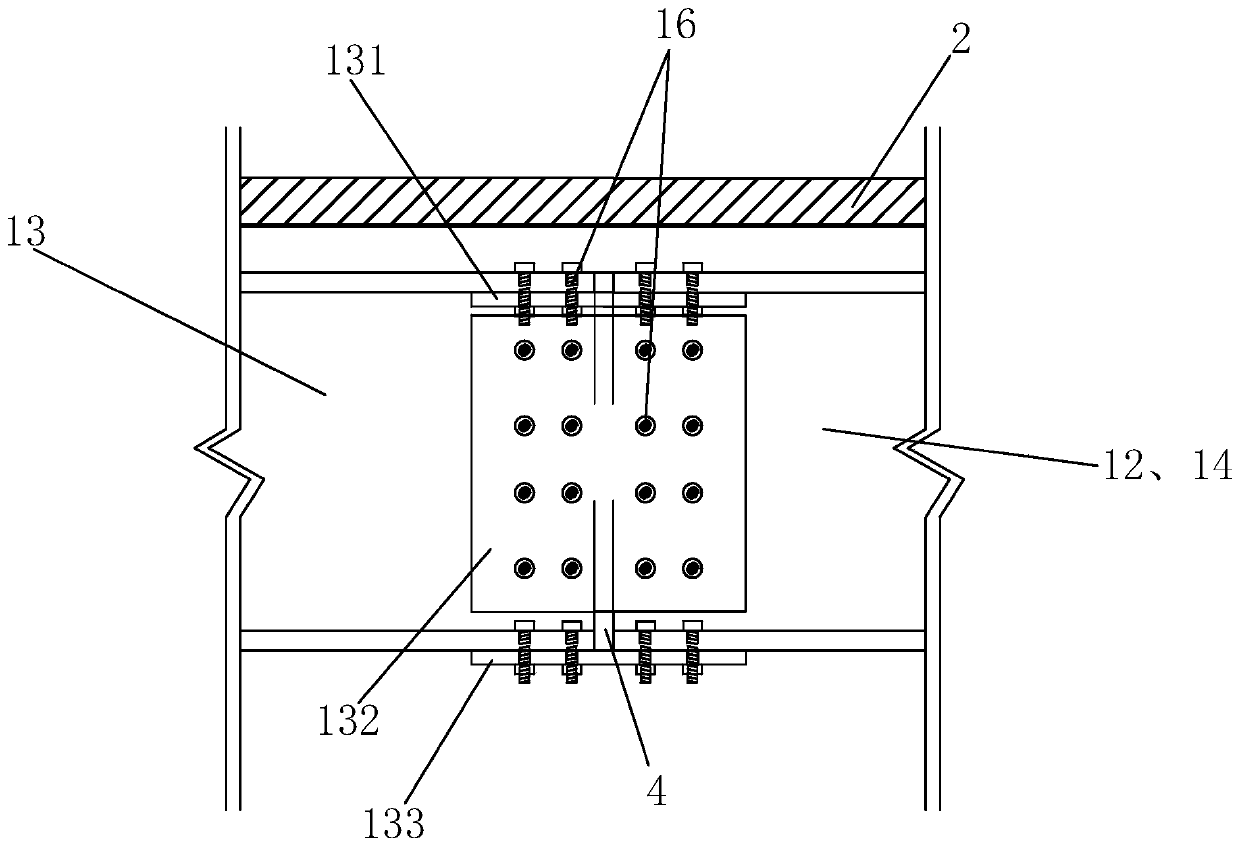
[0042] The structure and connection mode of this embodiment are basically the same as that of Embodiment 1, the difference is that: Figure 11 with 12 As shown, the lower ends of the first friction plate 17 and the second friction plate 18 are connected with the lower ends of the first and second end steel beams 11 and 15 and the lower ends of the first and second energy dissipation section steel beams 12 and 14 flush, the first end steel beam 11 and the first energy-dissipating section steel beam 12 and the second end steel beam 15 and the second energy-dissipating section steel beam 14 are connected through the lower flange splicing plate 133, And the lower flange splicing plate 133 passes through the first high-strength friction bolt 16 and the first end steel beam 11, the second end steel beam 15, the first energy-dissipating section steel beam 12 and the second energy-dissipating section steel beam 14 connected.


PUM


Abstract

The invention discloses a steel beam structure capable of being replaced due to earthquake damage. The steel beam structure comprises a combined steel beam and a combined floor slab connected with the combined steel beam, wherein the combined steel beam comprises a first end part steel beam, a first energy dissipation section steel beam, a middle section crossing steel beam, a second energy dissipation section steel beam and a second end part steel beam which are sequentially connected, the first end part steel beam and the second end part steel beam are respectively connected with end posts at the two sides, and all the steel beams are an I beam respectively and are easy to repair. Meanwhile, the repair cost is low, the construction period is short, and the steel beam structure is less restricted by climatic conditions.

Description

technical field [0001] The invention belongs to the technical field of building structures, and in particular relates to an earthquake-damaged replaceable steel beam structure. Background technique [0002] The traditional frame structure refers to the structural form of reinforced concrete columns-reinforced concrete beams, and the floor and beams are integrally poured. The self-weight of the structure is relatively large, while the traditional on-site construction method has a low degree of industrialization. The supporting formwork, maintenance, and formwork removal processes are cumbersome and generate a lot of construction waste. After the earthquake damage, the structure is difficult to repair or the repair cost is high. In contrast, the concrete column-steel beam composite structure has a lighter weight, which greatly reduces the cast-in-place operations, shortens the construction period, and is less restricted by climatic conditions. However, due to the existence of...

Claims


Application Information

Patent Timeline
Patent Type & Authority Patents(China)
IPC IPC(8): E04B1/24E04B1/58
CPCE04B1/24E04B1/2403E04B2001/2415E04B2001/2418E04B2001/2457E04B2001/2484
Inventor 刘阳郭子雄廖逸凡陈海黄群贤叶勇
Owner HUAQIAO UNIVERSITY
Why Eureka
Try Eureka