Improved Analytical Model of Motor Stator Core Vibration Caused by Magnetostriction

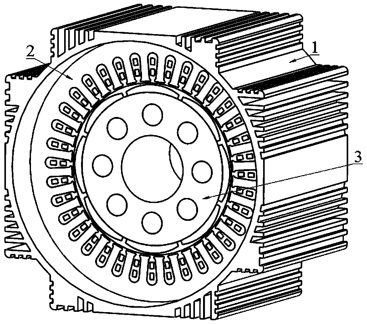
A stator core, motor stator technology, applied in the direction of electrical digital data processing, instrumentation, design optimization/simulation, etc., can solve the problem that the vibration displacement, stress and strain distribution characteristics of the motor stator core yoke cannot be calculated, and the core axis is not considered. Problems such as directional vibration and large computer resources, etc., to achieve accurate and reliable calculation results, fast calculation speed, and small calculation amount

Active Publication Date: 2019-12-27
SHENYANG POLYTECHNIC UNIV
View PDF7 Cites 0 Cited by
  • Summary
  • Abstract
  • Description
  • Claims
  • Application Information

AI Technical Summary

Problems solved by technology

Although the finite element method has high solution accuracy, it takes up too much computer resources, takes a long time to calculate, and the calculation results are easily affected by factors such as grid division.
At present, there is only one public document that uses the analytical method to study the electromagnetic vibration of the motor caused by magnetostriction, but this analytical calculation model only considers the two-dimensional in-plane vibration of the stator core of the motor, and does not consider the axial vibration of the core
At the same time, this method only considers the stress along the tangential direction of the stator core yoke ring, ignoring the radial and axial stresses. This simplified model can only calculate the average vibration of the motor yoke ring, and cannot Calculate the distribution characteristics of vibration displacement, stress and strain in the yoke of the stator core of the motor

Method used


Image

  • Improved Analytical Model of Motor Stator Core Vibration Caused by Magnetostriction
  • Improved Analytical Model of Motor Stator Core Vibration Caused by Magnetostriction
  • Improved Analytical Model of Motor Stator Core Vibration Caused by Magnetostriction

Examples


Embodiment

[0147] The invention uses the finite element method to verify the analytical calculation model of the motor stator core vibration caused by magnetostriction. Taking a 2.1kW radial flux amorphous alloy permanent magnet motor as an example for quantitative analysis, the 2.1kW motor has a rated frequency of 267Hz, 8 poles and 36 slots. The two methods used the same performance parameters during analysis. Use 2D finite element to analyze the electromagnetic field of permanent magnet motor, and establish a quarter-period model of the motor such as Figure 5 Shown. The tangential and radial magnetic flux density at point B of the stator core yoke of the motor is calculated as a function of time. Image 6 As shown, the radial and tangential magnetic flux density at point A of the motor stator core tooth position changes with time. Figure 7 Shown. From Image 6 with 7 It can be seen that the magnetic field of the stator core yoke of the motor is mainly tangential, and the magnetic fi...


PUM


Abstract

The invention discloses an improved analytical model of the vibration analysis model of the motor stator core caused by magnetostriction. According to the structure and magnetic field distribution characteristics of the radial flux motor, the stator core is divided into two sub-domains, the yoke part and the tooth part. The vibration of the yoke is the vibration of the ring body, and the vibration of the tooth is the vibration of the rectangular block. Based on the piezomagnetic equation and Newton's law, the radial and axial partial differential equations of stator core yoke and tooth vibration are respectively established. The vibration differential equation is solved by the separation of variables method, and the undetermined coefficients are solved according to the boundary conditions. The invention has accurate calculation results and clear physical concepts, can be used to calculate the vibration displacement, velocity, acceleration, stress and strain distribution characteristics of the motor stator core caused by magnetostriction, and is an effective motor vibration analysis method.

Description

Technical field [0001] The invention belongs to the technical field of motor electromagnetic vibration analysis, and specifically relates to an improved analytical model of motor stator core vibration caused by magnetostriction. Background technique [0002] The vibration and noise sources of the motor are mainly electromagnetic vibration noise sources, mechanical vibration noise sources and aerodynamic vibration noise sources. Electromagnetic vibration noise is divided into vibration noise caused by electromagnetic force and vibration noise caused by magnetostriction. In the existing research results, many scholars have ignored the magnetostrictive effect and focused on the electromagnetic vibration and noise caused by electromagnetic force. However, in recent years, with the continuous development of experimental testing technology, the gradual in-depth study of engineering application problems, and the continuous improvement of finite element calculations, especially the grad...

Claims


Application Information

Patent Timeline
Patent Type & Authority Patents(China)
IPC IPC(8): G06F17/50
CPCG06F30/23
Inventor 韩雪岩吴胜男佟文明贾建国陈健唐任远王凯东
Owner SHENYANG POLYTECHNIC UNIV
Why Eureka
Try Eureka