Optimal configuration method of distributed generations (DG) based on power moment algorithm

A distributed power supply, optimized configuration technology, applied in the direction of circuit devices, reactive power adjustment/elimination/compensation, electrical components, etc., can solve the problem that the configuration results are easily affected by the initial parameters, the method is complicated, and the random load distribution is not considered. question

Inactive Publication Date: 2011-08-24
HARBIN INST OF TECH
View PDF3 Cites 13 Cited by
  • Summary
  • Abstract
  • Description
  • Claims
  • Application Information

AI Technical Summary

Problems solved by technology

[0004] The purpose of the present invention is to provide a distributed power supply optimization configuration method based on the power moment method to solve the situation that the existing technology can only consider the uniform load distribution characteristics or constant power factor load, or the configuration result is easily affected by the initial parameters, or It does not take into account the fact that the load distribution in the actual distribution network is often random, and most of the methods are very complicated

Method used


Image

  • Optimal configuration method of distributed generations (DG) based on power moment algorithm
  • Optimal configuration method of distributed generations (DG) based on power moment algorithm
  • Optimal configuration method of distributed generations (DG) based on power moment algorithm

Examples


specific Embodiment approach 1

[0013] Specific implementation mode one: this implementation mode comprises the following steps:

[0014] Step 1: Perform initial power flow calculation for the given distribution network connection structure, parameters of each branch, load power of each node and node voltage of the substation, and obtain the sum of the voltage of each node and the system active network loss before the distributed power supply is connected. Branch power, given the number m of distributed power access;

[0015] Step 2: Calculate the second moment of active power of each node, and arrange the values ​​of the second moment of active power from large to small, and select the nodes whose values ​​are in the first m as the position for configuring the power supply;

[0016] Step 3: Calculate the active primary moment of the m nodes according to the known number m of distributed power supply connections and the first m node positions determined by the active second moment, and solve m equations to o...

specific Embodiment approach 2

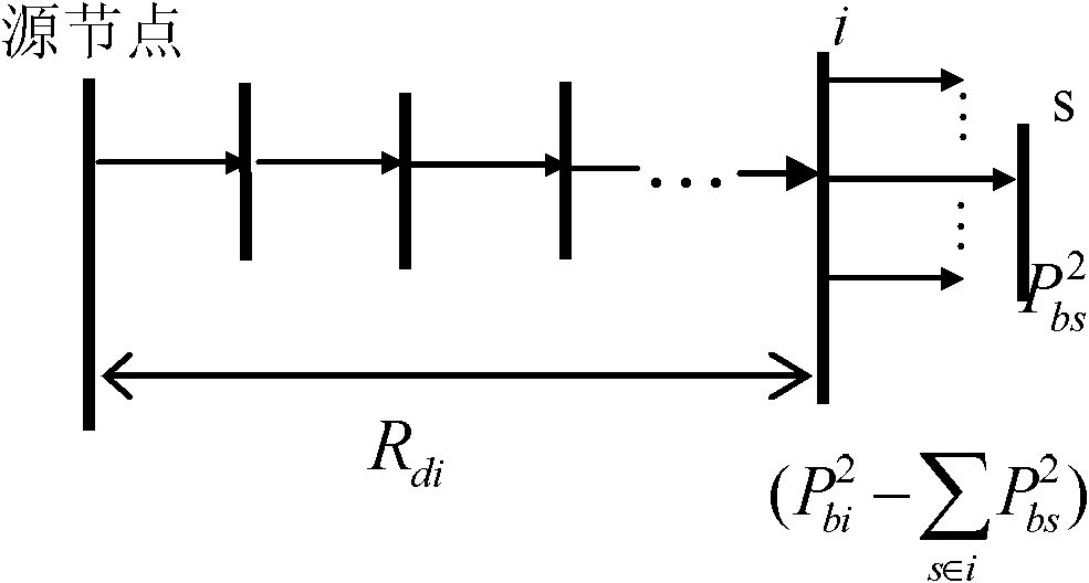
[0094] Specific embodiment two: the feature of this embodiment is that in step two, the active second moment is obtained by the following formula:

[0095] T P 2 ( i ) = R di × ( P bi 2 - Σ s ∈ i P bs 2 )

[0096] Among them, R di It is the sum of all branch resistances encountered upstream from the i-node to the source node.

[0097] P bi is the branch active power flowing into node i, obtained according to the power flow calculation result in step 1;

[0098] P bs is the branch active power flowing into node s, node s is the child node of node i, P bs Obtai...

specific Embodiment approach 3

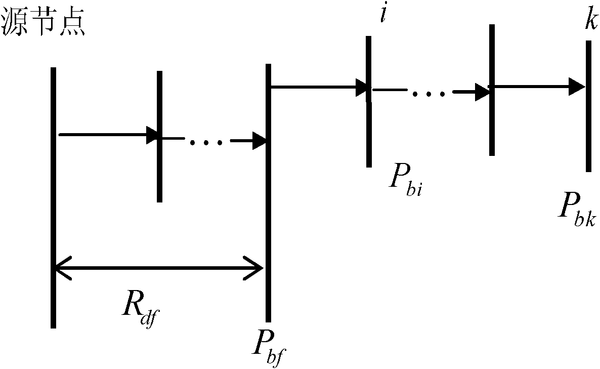
[0102]Specific embodiment three: the characteristic of this embodiment is that the active primary moment in step three can be calculated as follows:

[0103] T P 1 ( k ) = Σ i ⊇ k R df ( P bf - P bi ) + R dk P bk

[0104] where R df Indicates the electrical distance expressed in resistance from the parent node f of the i node to the source node, which can be calculated as follows:

[0105] R df = Σ j ⊇ f r j

[0106] R dk Indicates the electrical...


PUM


Abstract

The invention provides an optimal configuration method of distributed generations (DG) based on a power moment algorithm and relates to a configuration method for accessing the DGs to a power distribution network, which is utilized to solve the problems that a uniform load distribution characteristic or a constant power factor load condition is considered only, or a configuration result is influenced easily by initial parameters, or a condition of random load distribution in an actual power distribution network is not considered, and existing methods are complicated in the prior art. The optimal configuration method of the DGs provided the invention is utilized to respectively define active second moment and active first moment with the beginning of the minimum target function of network loss, thus a power moment method for optimally configuring the DGs is put forward, which comprises the following steps: determining the installation positions of the DGs in accordance with the active second moment; determining active optimization of the DGs in accordance with the active first moment; and determining reactive optimization or compensated reactive capacity of the DGs in accordance with reactive first moment. The method can be also applied to determining the problems of real-time active output power and reactive output power of each DG in real-time scheduling.

Description

technical field [0001] The invention relates to a configuration method for connecting distributed power sources to a power distribution network. Background technique [0002] Distributed power generation technology using renewable energy as primary energy meets the requirements of human beings to develop a low-carbon economy and achieve sustainable development in the 21st century, so it has attracted great attention worldwide. The access of distributed generation (distributed generation, DG) makes the power distribution system change from a passive network to an active network. Therefore, it is very important to choose the installation location and capacity of distributed power reasonably. [0003] Many scholars at home and abroad have studied the problem of DG configuration optimization from different angles, and obtained some research results. In summary, they can be roughly divided into three categories: one is traditional mathematical optimization methods including ana...

Claims


Application Information

Patent Timeline
Patent Type & Authority Applications(China)
IPC IPC(8): H02J3/00H02J3/18
CPCY02E40/30
Inventor 蔡中勤刘明基周苏荃张伟刘鹏柳静
Owner HARBIN INST OF TECH
Why Eureka
Try Eureka