Phase shifter transmission device

A transmission device and phase shifter technology, which is applied to electrical components, antennas, etc., can solve the problems of stuck, long lateral transfer distance, and wide arrangement of multi-frequency antenna phase shifters, so as to reduce installation volume and effectively utilize The effect of space and flexible layout

Inactive Publication Date: 2017-02-08
TONGYU COMM INC
View PDF3 Cites 10 Cited by
  • Summary
  • Abstract
  • Description
  • Claims
  • Application Information

AI Technical Summary

Problems solved by technology

[0002] At present, the antenna transmission of ESC base stations in domestic and foreign markets mainly adopts one-to-one transmission mode, that is, one motor controls one phase shifter. With the development of communication, multi-frequency antennas have become the mainstream trend. The phase shifter will also increase accordingly, and the width of the antenna will also increase. The scheme of driving a phase shifter by one transmission is obviously not suitable for the development of multi-frequency antennas. The integrated development of the transmission solves the problems of large space occupation and high cost, but With the increase of the antenna width, there are transfer problems. The large transfer distance leads to a series of defects such as large friction force of the tie rod, large deformation of the transfer plate, and even jamming.
[0003] The technical problem solved by the present invention is to provide a detachable modular two-drive multi-rod transmission device, which aims to solve the problems of wide arrangement of multi-frequency antenna phase shifters, long horizontal transfer distance, poor precision, friction, etc.

Method used


Image

  • Phase shifter transmission device
  • Phase shifter transmission device
  • Phase shifter transmission device

Examples


Embodiment Construction

[0024] The present invention will be described in detail below in conjunction with the accompanying drawings and embodiments.

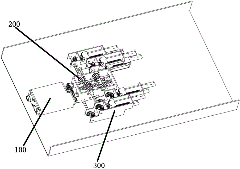
[0025] The phase shifter transmission device of the embodiment of the present invention includes: RCU motor part 100, position selection part 200 and pull rod part 300, wherein, RCU motor part 100 is pluggably connected with position selection part 200, and position selection part 200 can also be It is connected with the tie rod part 300 in a plug-in manner.

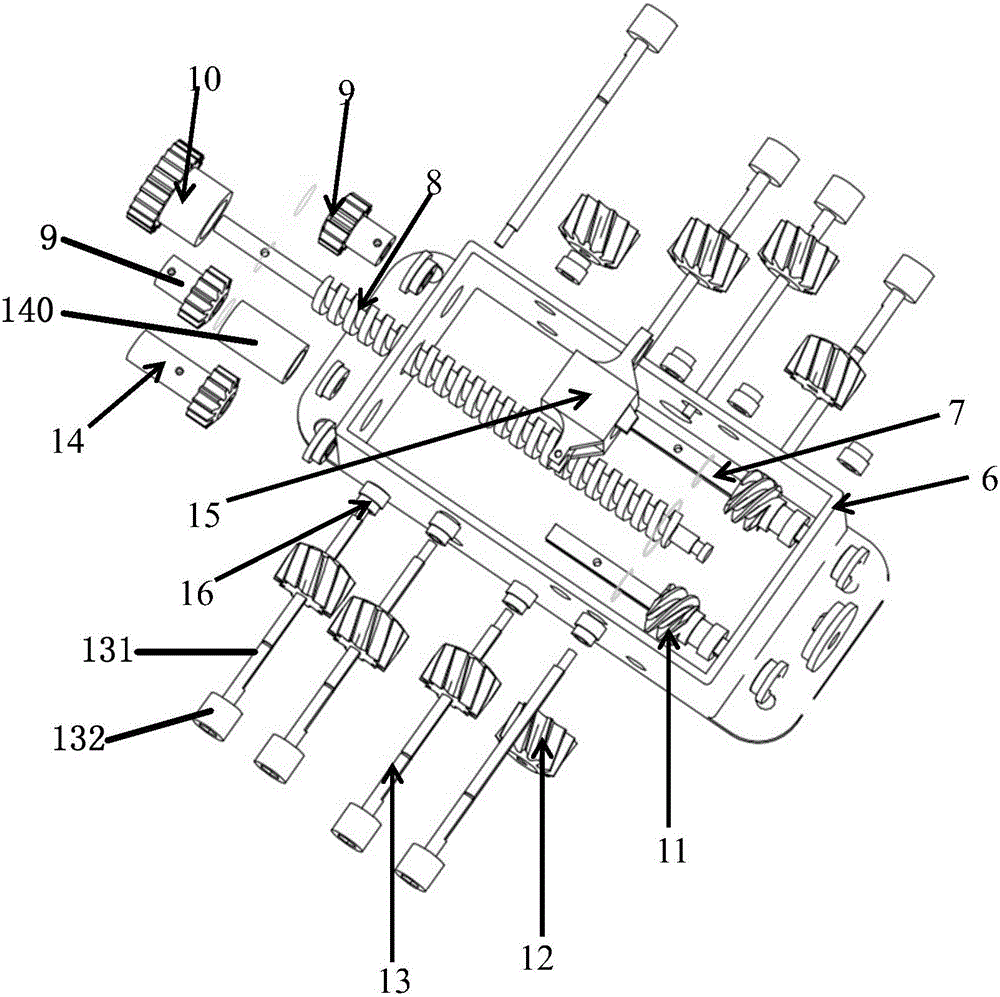
[0026] In a specific application embodiment, the position selection component 200 includes: a cavity 6, a second screw 8 and at least one sliding rod 7 that are rotatably connected to an opposite side wall of the cavity 6, and the sliding rod 7 is arranged in parallel The second screw 8 side. Preferably, a pair of sliding rods 7 can be assembled symmetrically and parallelly on both sides of the second screw rod 8 . Wherein, the second screw rod 8 is sleeved with a second nut 15 that can linear...


PUM


Abstract

The invention discloses a phase shifter transmission device which comprises a pull rod component. The pull rod component comprises a pull rod, a supporting frame and at least two first transmission assemblies. The supporting frame is provided with an upper supporting layer and a lower supporting layer. Each supporting layer is provided with at least one first transmission assembly. The first transmission assembly comprises a first screw, a first nut which sleeves the first screw and can perform linear reciprocation in a length direction, and a first gear which is rigidly connected with one end of the first screw and has a rotation direction that is same with that of the first screw. The pull rod is detachably connected with the first nut. The first gear is driven by an external transmission force for driving the first screw to rotate so that the first nut drives the pull rod to move in the length direction of the first screw, and furthermore displacement of the phase shifter which is connected with the pull rod can be adjusted. Through the technical solution of the invention, the phase shifter provided by the invention realizes advantages of settling a problem of large area occupation by the phase shifter in flat placement, reducing mounting volume of the phase shifter transmission device and improving transmission precision.

Description

technical field [0001] The invention relates to the technical field, in particular to a phase shifter transmission device. Background technique [0002] At present, the antenna transmission of ESC base stations in domestic and foreign markets mainly adopts one-to-one transmission mode, that is, one motor controls one phase shifter. With the development of communication, multi-frequency antennas have become the mainstream trend. The phase shifter will also increase accordingly, and the width of the antenna will also increase. The scheme of driving a phase shifter by one transmission is obviously not suitable for the development of multi-frequency antennas. The integrated development of the transmission solves the problems of large space occupation and high cost, but With the increase of the antenna width, there is a problem of transfer. The large transfer distance leads to a series of defects such as large friction force of the tie rod, large deformation of the transfer plate...

Claims


Application Information

Patent Timeline
Patent Type & Authority Applications(China)
IPC IPC(8): H01Q3/32
CPCH01Q3/32
Inventor 王斌钟欢欢成钢吴鹏方铁勇张理栋岳彩龙石磊刘木林
Owner TONGYU COMM INC
Why Eureka
Try Eureka