
Unmanned aerial vehicle based cleaning robot

A cleaning robot and unmanned aerial vehicle technology, applied in the field of cleaning robots, can solve the problems of being unable to clean up cobwebs and dust, and achieve the effects of easy promotion and use, reducing external obstacles, reducing costs and storage space

Inactive Publication Date: 2017-02-15
广西电网有限责任公司崇左供电局
View PDF6 Cites 16 Cited by
  • Summary
  • Abstract
  • Description
  • Claims
  • Application Information

AI Technical Summary

Problems solved by technology

[0004] However, the current sweeping robot can only clean the garbage on the ground; there is no way to clean the cobwebs and dust on the roof

Method used


Image

  • Unmanned aerial vehicle based cleaning robot
  • Unmanned aerial vehicle based cleaning robot
  • Unmanned aerial vehicle based cleaning robot

Examples


Embodiment 1

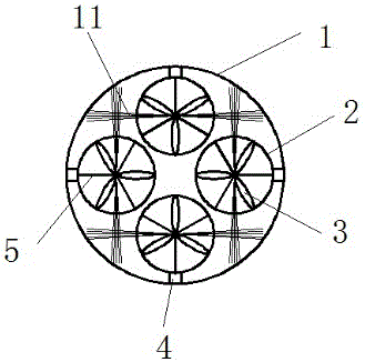
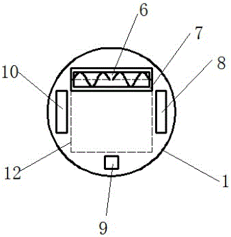
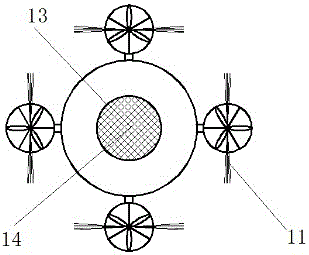
[0040] A cleaning robot based on an unmanned aerial vehicle, which includes a circular robot body 1, a dust collection chamber 12 is arranged inside the robot body 1, a dust suction fan is arranged in the dust collection chamber 12, and a dust collection fan is arranged at the bottom of the robot body 1. There are driving wheels, a dust collection chamber entrance 7 and a rolling brush 6; the ash collection chamber entrance 7 is located at the front end of the bottom of the robot body 1, and the ash collection chamber entrance 7 is placed at the ash collection chamber entrance 7, and the rolling brush 6 is in contact with the ground; A number of foldable rotor mechanisms are arranged around the top of the robot body 1, and the rotor mechanisms are evenly arranged along the circumference of the top of the robot body 1; the top of the rotor mechanism is provided with a side brush 11 that rotates synchronously with the rotor mechanism.

[0041] The number of the rotor mechanisms c...

Embodiment 2

[0049] This embodiment is substantially the same as Embodiment 1, the difference being that the brushes 6 are provided with spirally arranged brushes; There is a gap that is not covered by the brush, and the rotation direction of the left and right brushes is different.

[0050] The left and right two-section brushes are used with different rotation directions, which can gather the dust or garbage at the two ends of the roller brush to the middle of the roller brush, so as to facilitate the suction fan to suck the dust or garbage into the ash collection chamber.

Embodiment 3

[0052] This embodiment is substantially the same as Embodiment 1 and Embodiment 2, and the other difference lies in that the side brush 11 is inclined upward by 5-30° so that it forms a cone shape after being rotated.

[0053] The side brush can be tilted up to better clean the roof, avoiding the top of the robot from touching the roof.


PUM


Abstract

The invention relates to the field of robots, and discloses an unmanned aerial vehicle based cleaning robot. The unmanned aerial vehicle based cleaning robot includes a circular robot body; a dust collection chamber is arranged in the robot body; a dust suction fan is arranged in the dust collection chamber; drive wheels, a first inlet of the dust collection chamber and a rolling brush are arranged on the bottom of the robot body; the first inlet of the dust collection chamber is formed in the front end of the bottom of the robot body; the rolling brush is arranged in the first inlet of the dust collection chamber and contacts a ground surface; a second inlet of the dust collection room is formed in the center of the top of the robot body, and a filtering screen is arranged on the second inlet of the dust collection chamber; a plurality of foldable rotation wing mechanisms are arranged on the periphery of the top of the robot body, and the rotation wing mechanisms are evenly arranged along the circumference of the top of the robot body; and edge brushes which can synchronously rotate with the rotation wing mechanisms are arranged on the tops of the rotation wing mechanisms. The cleaning robot can clean trashes on a floor like the common sweeping robots, and can clean spider webs and dust on a roof.

Description

technical field [0001] The invention relates to the field of robots, in particular to a cleaning robot based on an unmanned aerial vehicle. Background technique [0002] With the development of robot technology, robots can only be used in industry and national defense before, and they are gradually turned into civilian use. They gradually enter people's families and people's lives, bringing convenience to people's lives. , Improve people's work efficiency and save manpower and material resources. [0003] Sweeping robot is the most popular robot in people's life, and it is a new generation of family nanny! It can clean the hair, melon seed shell, dust and other garbage in the room. With the development of robot technology, the robot will become an indispensable item in people's life in the future, just like washing machines and rice cookers. [0004] However, the current sweeping robot can only clean the garbage on the ground; there is no way to clean the cobwebs and dust...

Claims


Application Information

Patent Timeline
Patent Type & Authority Applications(China)
IPC IPC(8): A47L11/38B25J11/00B64C27/08B64C39/02
CPCA47L11/38B25J11/0085B64C27/08B64C39/024
Inventor 蒋浪
Owner 广西电网有限责任公司崇左供电局
Learn More