
Gas overflowing type gas liquid reaction equipment

A technology of gas-liquid reaction and overflow type, which is applied in the direction of chemical methods, dissolution, mixers, etc. that make liquids and gaseous media react, and can solve problems such as energy loss, low reaction efficiency, and long reaction time, and achieve contact Increase the area, increase the contact area, and solve the effect of large energy consumption

Inactive Publication Date: 2017-02-15
南京东擎科技有限公司
View PDF2 Cites 0 Cited by
  • Summary
  • Abstract
  • Description
  • Claims
  • Application Information

AI Technical Summary

Problems solved by technology

[0002] Gas-liquid reaction is one of the common reactions in the chemical industry. The traditional equipment on the market uses stirring to promote the liquid to fully react in the gas environment. However, due to the limitation of the contact area between the gas and the liquid, the reaction efficiency is relatively low. It is difficult to meet the needs of actual production, and it takes a lot of reaction time, and the nature of liquid stirring needs to be driven by a stirring motor. After a long time of reaction, the stirring motor is prone to failure, and a long time of work will consume a lot of energy.

Method used


Image

  • Gas overflowing type gas liquid reaction equipment
  • Gas overflowing type gas liquid reaction equipment

Examples


Embodiment 1

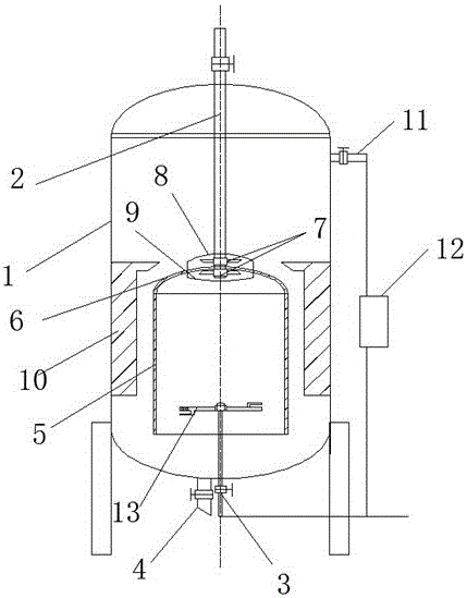
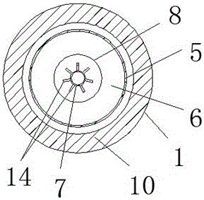
[0014] Embodiment 1: as figure 1 and 2 Shown is a kind of overflow type gas-liquid reaction equipment, the described reaction equipment is a sealed housing 1, the top of the housing 1 is provided with a liquid inlet pipe 2, and the bottom of the housing 1 is provided with an air inlet pipe 3 and a discharge pipe. Pipe 4, the middle part of the housing 1 is provided with a cylindrical overflow tube 5, the top of the overflow tube 5 is provided with an arc-shaped sealing top cover 6, and the bottom of the overflow tube 5 communicates with the housing 1, The liquid inlet pipe 2 is connected to the sealing top cover 6, and the outside and the inside of the sealing top cover 6 are provided with a symmetrically installed liquid separator disc 7, and the liquid separator disc 7 is connected to the liquid inlet pipe 2, and the liquid separator 7 is connected to the liquid inlet pipe 2. A plurality of liquid pipes 14 are uniformly distributed on the liquid separating disk 7, and the t...

Embodiment 2

[0015] Embodiment 2: as figure 1 and 2 As shown, the liquid separating disc 7 above the sealing top cover 6 is provided with a downwardly curved arc-shaped shunt baffle 8, and the liquid separating disc 7 below the sealing top cover 6 is provided with an upwardly curved secondary arc-shaped divider. Liquid baffle 9; through the combination of the arc-shaped shunt baffle 8 and the secondary arc-shaped liquid-separating baffle 9, the liquid discharged from the liquid-distributing disk 7 above the sealing top cover 5 is guaranteed to flow downward, and the liquid below the sealing top cover 5 is divided The liquid discharged from the liquid disc 7 flows upwards, so that the discharged liquid flows down slowly along the side wall of the overflow tube 5 .

Embodiment 3

[0016] Embodiment 3: as figure 1 and 2 As shown, the upper part of the housing 1 is provided with an exhaust pipe 11, and the exhaust pipe 11 is connected to the intake pipe 3 through an air pump 12 and a return line; The return pipe is used for backflow, which is convenient for making full use of the gas.


PUM


Abstract

The invention discloses gas overflowing type gas liquid reaction equipment, which is a sealed casing, wherein the top of the casing is provided with a liquid inlet pipe; the bottom of the casing is provided with a gas inlet pipe and a discharging pipe; the middle part of the casing is provided with a cylindrical overflow tube; the top of the overflow tube is provided with a circular arc-shaped sealed top cover; the bottom of the overflow tube communicates with the casing; the liquid inlet pipe is connected onto the sealed top cover; a liquid distribution circular disc in symmetrical installation are arranged outside and inside the sealed top cover; the liquid distribution circular disc communicates with a liquid inlet pipe; a plurality of liquid distribution pipes are uniformly distributed in the liquid distribution circular disc; the top of the air inlet pipe is provided with a gas flow stirring paddle; an air inlet pipe communicating with the gas spraying opening is arranged on the gas flow stirring paddle; the gas flow stirring paddle is arranged at the inner side of the overflow tube. Through the overflow tube added at the casing, reaction liquid slowly flows from the side walls of both of the inner side and the outer side of the overflow tube; reaction gas is introduced to the inner side of the overflow tube, so that the contact area of the gas and the liquid at the inner side and the outer side of the tube body is greatly improved; the device is used for auxiliary stirring for the gas flow stirring paddle; the problem of great energy consumption of a stirring motor is solved.

Description

technical field [0001] The invention relates to the uniform reaction technology of different media, in particular to an overflow gas-liquid reaction equipment. Background technique [0002] Gas-liquid reaction is one of the common reactions in the chemical industry. The traditional equipment on the market uses stirring to promote the liquid to fully react in the gas environment. However, due to the limitation of the contact area between the gas and the liquid, the reaction efficiency is relatively low. It is difficult to meet the needs of actual production, and it takes a lot of reaction time, and the nature of liquid stirring needs to be driven by a stirring motor. After a long time of reaction, the stirring motor is prone to failure, and a long time of work will consume a lot of energy. Contents of the invention [0003] In view of the above existing problems, the purpose of the present invention is to provide a spilled gas-liquid reaction equipment with simple structure...

Claims


Application Information

Patent Timeline
IPC IPC(8): B01J10/00B01F13/02B01F33/40
CPCB01J10/00B01F33/40
Inventor 牛冀峰何文超
Owner 南京东擎科技有限公司
Learn More