A capacitor forming machine

A molding machine and capacitor technology, applied in the field of capacitor molding machines, can solve the problems of cost, difficulty in quality assurance, and the inability of capacitors to be inserted into circuit boards, so as to reduce costs, improve efficiency, and improve product consistency.

Active Publication Date: 2018-06-05
JIANGMEN HONGYI BATTERY
View PDF5 Cites 0 Cited by
  • Summary
  • Abstract
  • Description
  • Claims
  • Application Information

AI Technical Summary

Problems solved by technology

[0002] Capacitors are generally called capacitors directly, and are one of the electronic components widely used in electronic equipment. Some capacitors are provided with a pin on both sides. Usually, capacitors are bent into such Figure 5 shape shown, and then soldered on the board, while capacitors are produced in shapes such as Image 6 As shown, multiple capacitors are arranged in a row, and the pins at both ends are connected to a connecting board. The traditional method is that the worker cuts the pins of the capacitor according to the required length, then bends them manually, and then according to the hole spacing on the circuit board Adjusting the distance between the two pins is inefficient and consumes a lot of time and labor costs. The consistency of manual operation is poor, and the quality is difficult to guarantee. It is prone to the problem that the capacitor cannot be inserted into the circuit board, which will affect the subsequent welding process.

Method used


Image

  • A capacitor forming machine
  • A capacitor forming machine
  • A capacitor forming machine

Examples


Embodiment Construction

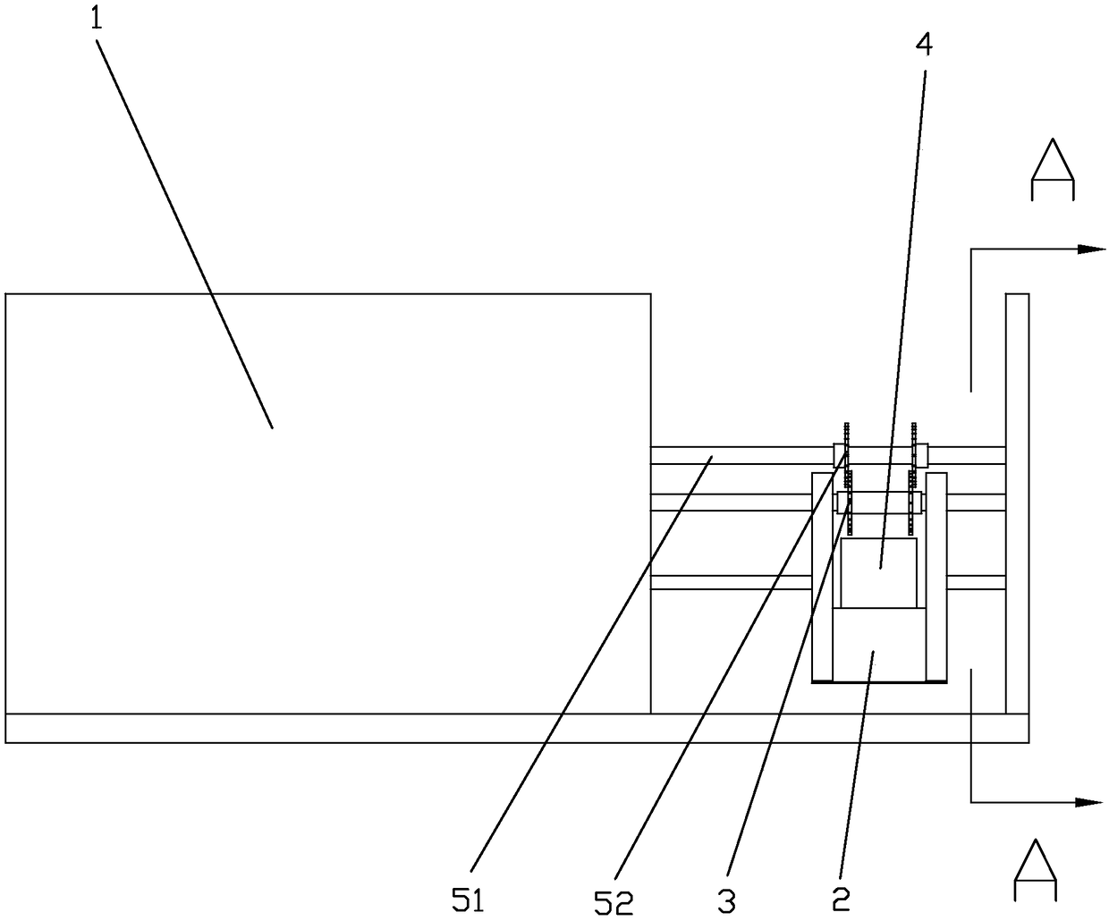
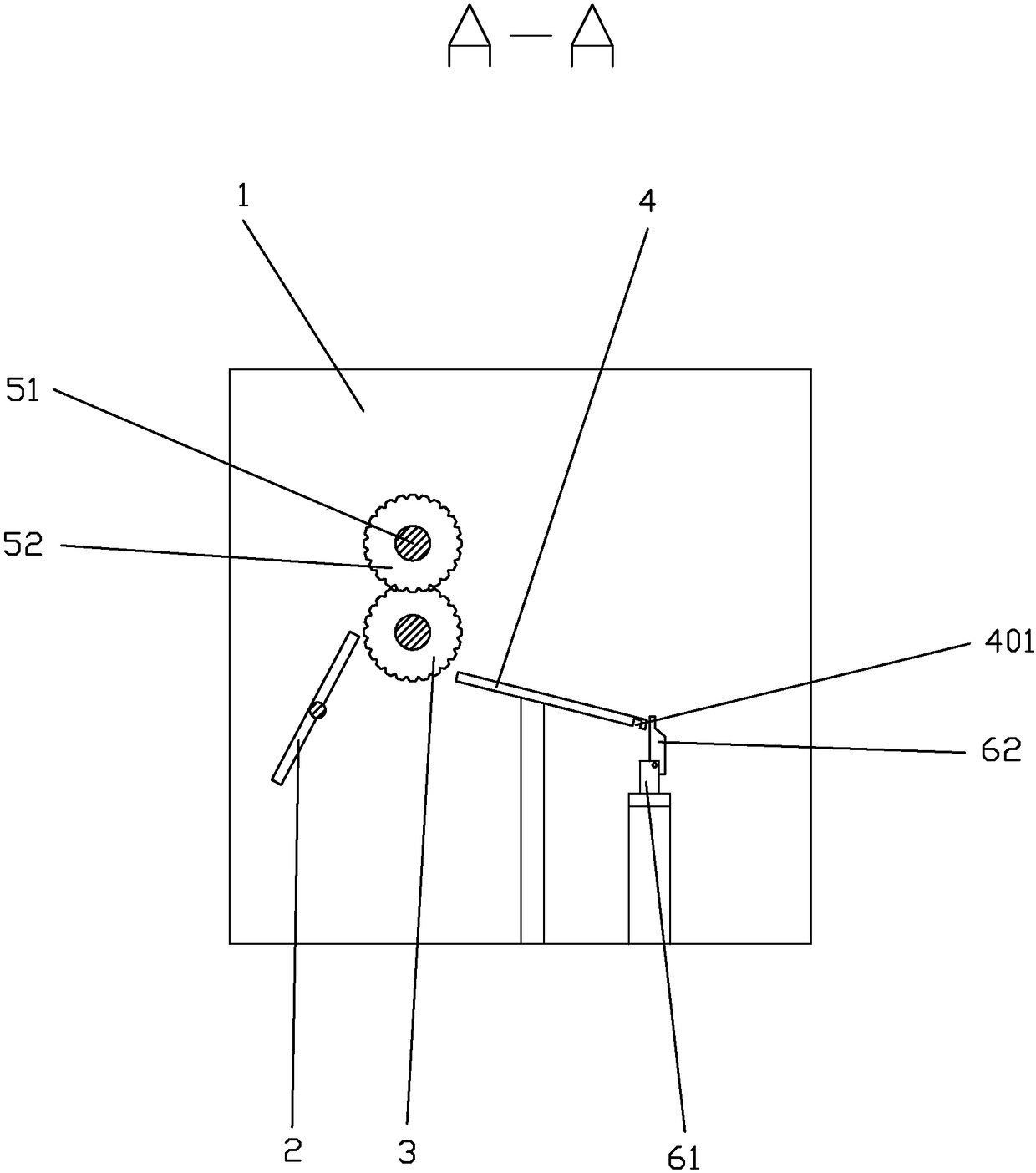
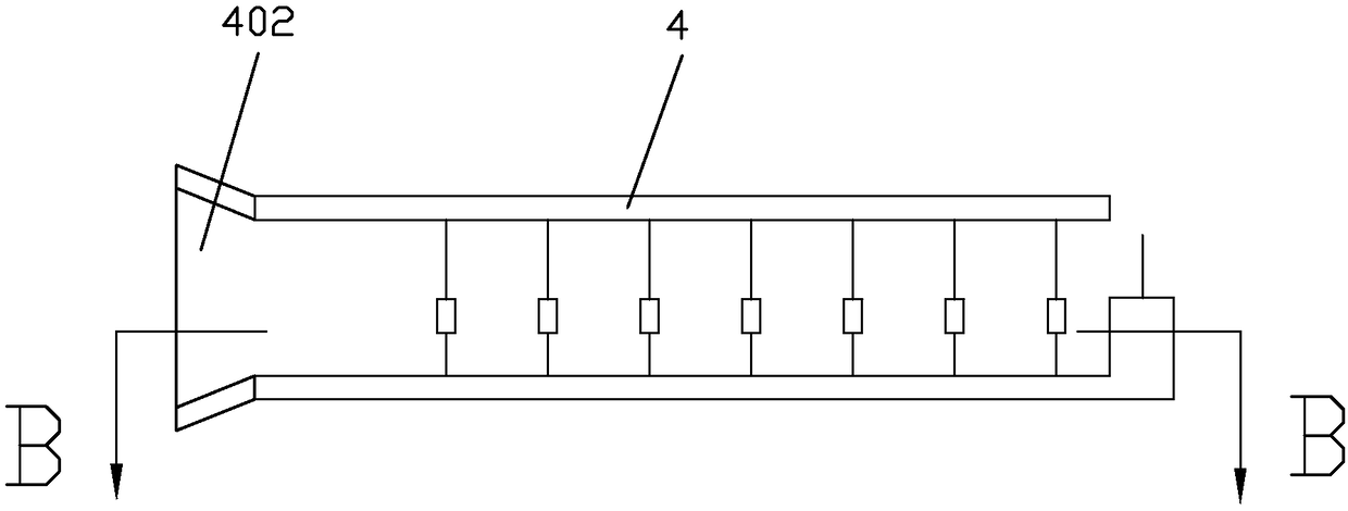
[0019] refer to Figure 1~Figure 4 , a capacitor forming machine, including a main machine 1, a conveying guide rail 2, a cutter device, a first conveying gear 3, a rear conveying guide rail 4 and a bending forming device, the rear end of the conveying guide rail 2 is close to the first conveying gear 3 , the conveying guide rail 2 is provided with a slot consistent with the width of the capacitor row, the tooth pitch of the first conveying gear 3 is consistent with the interval of the capacitor in the capacitor row, the cutter device includes a rotating shaft 51 and is installed on the rotating shaft 51 Two shearing gears 52, the two shearing gears 52 separate the two sides of the first conveying gear 3 and close to the first conveying gear 3, the size of the shearing gear 52 and the first conveying gear 3, the number of teeth The same and rotate in different directions, the shearing gear 52 is tangent to the dedendum circle of the first conveying gear 3; the rear conveying g...


PUM


Abstract

The invention discloses a capacitor forming machine. The capacitor forming machine comprises a main engine, a conveying guide rail, a cutter device, a first conveying gear, a rear conveying guide rail and a bending forming device; the rear end of the conveying guide rail is close to the first conveying gear, the conveying guide rail is provided with a clamping groove consistent with a capacitor row in width, the cutter device comprises a rotating shaft and two shearing gears mounted on the rotating shaft, the shearing gears and the first conveying gear are the same in size and tooth number and rotate in the different directions, and the shearing gears are tangent with the root circle of the first conveying gear; the rear conveying guide rail is provided with a conveying groove consistent with the capacitor row in width, a groove with a downward opening is formed in the rear end of the rear conveying guide rail, the groove is communicated with a conveying groove, and the width of the groove is smaller than the length of a formed capacitor; the bending forming device comprises a rotation shaft and a bending plate eccentrically mounted on the rotation shaft, and the rotation shaft is arranged under the groove; and power of the first conveying gear, power of the rotating shaft and power of the rotation shaft are all from the main engine.

Description

technical field [0001] The invention relates to a capacitor forming machine. Background technique [0002] Capacitors are generally called capacitors directly, and are one of the electronic components widely used in electronic equipment. Some capacitors are provided with a pin on both sides. Usually, capacitors are bent into such Figure 5 shape shown, and then soldered on the board, while capacitors are produced in shapes such as Figure 6 As shown, multiple capacitors are arranged in a row, and the pins at both ends are connected to a connecting board. The traditional method is that the worker cuts the pins of the capacitor according to the required length, then bends them manually, and then according to the hole spacing on the circuit board Adjusting the distance between the two pins is inefficient and consumes a lot of time and labor costs. However, the consistency of manual operation is poor, the quality is difficult to guarantee, and it is prone to the problem that the...

Claims


Application Information

Patent Timeline
Patent Type & Authority Patents(China)
IPC IPC(8): B21F11/00B21F1/00
CPCB21F1/00B21F11/00
Inventor 杨长明
Owner JIANGMEN HONGYI BATTERY
Why Eureka
Try Eureka