Robot joint system

A technology for robot joints and oil supply systems, which is used in manipulators, manufacturing tools, joints, etc.

Active Publication Date: 2017-02-15
UNIV OF JINAN
View PDF7 Cites 2 Cited by
  • Summary
  • Abstract
  • Description
  • Claims
  • Application Information

AI Technical Summary

Problems solved by technology

In short, it will take some time for the new generation of robot joints to achieve a major breakthrough in theory, and there are still many obstacles on the road to practical application.

Method used


Image

  • Robot joint system
  • Robot joint system
  • Robot joint system

Examples


Embodiment Construction

[0014] The present invention will be specifically described below in conjunction with the accompanying drawings and embodiments.

[0015] The invention is a robot joint system based on electro-hydraulic direct drive technology.

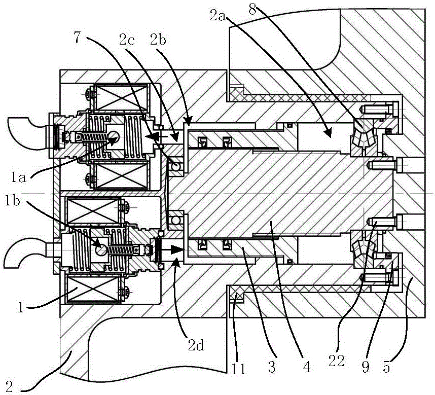
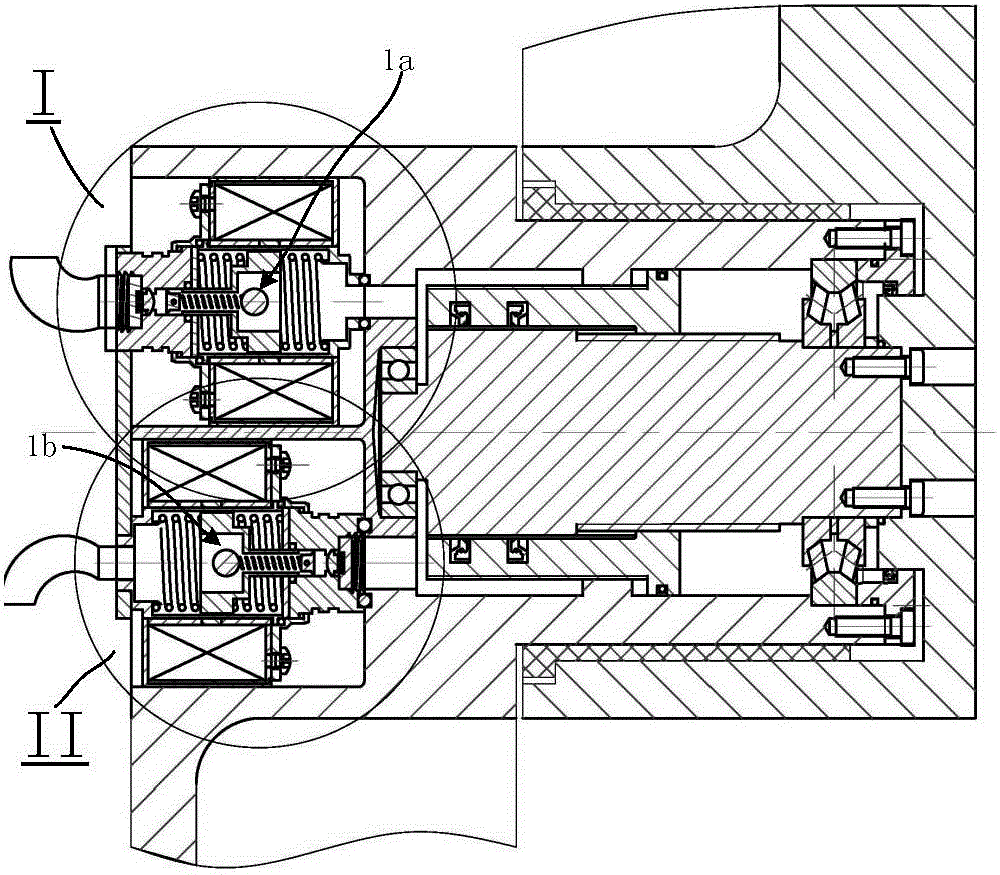
[0016] figure 1 It is a front view of the overall structure of the present invention.

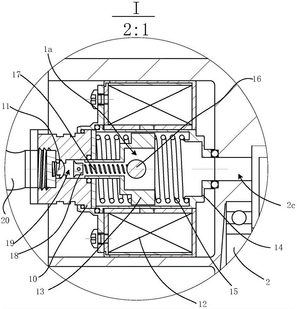
[0017] figure 2 It is a partially enlarged schematic diagram of the present invention.

[0018] The present invention includes a resonance oil supply system 1, a lower mechanical arm 2, a cylinder piston rod 3, a screw shaft 4, and an upper mechanical arm 5; the resonance oil supply system 1 is composed of a resonance oil supply system 1a and a resonance oil supply system 1b, The resonance oil supply system 1a and the resonance oil supply system 1b are symmetrically and reversely installed inside the lower mechanical arm 2. The lower mechanical arm 2 includes a right oil chamber 2a and a left oil chamber 2b. The oil inlet sleeve 14 of the resonance oil supply s...


PUM


Abstract

The invention discloses a robot joint system. The system comprises resonant oil supply systems 1 (including 1a and 1b), a lower mechanical arm 2, a cylinder piston rod 3, a screw shaft 4 and an upper mechanical arm 5, wherein the resonant oil supply systems 1a and 1b are symmetrically and reversely installed inside the lower mechanical arm 2; the lower mechanical arm 2 comprises a right oil chamber 2a and a left oil chamber 2b; an oil inlet jacket 14 of the resonant oil supply system 1a is communicated with the left oil chamber 2b via an oil hole 2c; an oil outlet jacket 10 of the resonant oil supply system 1b is communicated with the left oil chamber 2b via an oil hole 2d; the screw shaft 4 is installed inside the lower mechanical arm 2; internal and external threads of the cylinder piston rod 3 are respectively matched with an external thread of the screw shaft 4 and an internal thread hole of the lower mechanical arm 2; the screw shaft 4 is driven by hydraulic oil to swing; the upper mechanical arm 5 is installed at the shaft end of the lower mechanical arm 2 via a sliding bearing 11 and is fixed at the right side of the screw shaft 4. The system has the beneficial effect that the flexibility and compactness of robot joints are improved through reasonable integration of the resonant oil supply systems, a screw swing cylinder and the joint screw shaft.

Description

technical field [0001] The invention relates to a robot joint system, in particular to a robot joint system with electro-hydraulic direct drive technology. Background technique [0002] At present, robot technology is developing rapidly in the direction of becoming more and more intelligent. Since the first industrial robot was born in the United States in 1962, various robots have been distributed in various fields of society, not only in their appearance and function, but also in their core motion control system. It is also constantly changing. With the emergence of high-performance processor technology and the application of advanced theories such as artificial intelligence, fuzzy control, and neural networks, the control system of robots is also becoming more and more perfect. [0003] An extremely important part of the robot is the robot joint (or actuator). The robot joint is the basic unit of the robot. The overall performance of the robot is directly determined by t...

Claims


Application Information

Patent Timeline
Patent Type & Authority Applications(China)
IPC IPC(8): B25J17/00
CPCB25J17/00
Inventor 陈乃建韩祥东李恒春张睿
Owner UNIV OF JINAN
Why Eureka
Try Eureka